Linear Advance
Under default conditions, extruder axis movement is treated in the same way as the XYZ linear axes. The extruder motor moves in linear proportion to all the other motors, maintaining exactly the same acceleration profile and start/stop points. But an extruder is not a linear system, so this approach leads, most obviously, to extra material being extruded at the end of each linear movement.
Take the common test-cube as an example. Even with the best tuning the corners aren’t usually sharp, but bleed out. The top solid infill displays roughness where the print direction changes on perimeters. Such problems are minor or even imperceptible at low printing speeds, but they become more noticeable and problematic as print speeds increase.
Tuning flow and retraction can help, but this may lead to under-extrusion when starting new lines. Some slicers include an option to end extrusion early in each move, but this adds more complexity to the G-code and has to be re-tuned for different temperatures and materials.
Since the root cause is pressure, LIN_ADVANCE de-couples extrusion from the other axes to better control material pressure inside the nozzle, adapting to the printing speed. Once Linear Advance is properly tuned, bleeding edges and rough solid infill should be nearly eliminated.
Advantages
- Better dimensional precision due to reduced bleeding edges.
- Higher printing speeds are possible without any loss of print quality - as long as your extruder can handle the needed speed changes.
- Visible and tangible print quality is increased even at lower printing speeds.
- No need for high acceleration and jerk values to get sharp edges.
Special notes for v1.5
Changelog
- K is now a meaningful value with the unit [mm of filament compression needed per 1mm/s extrusion speed] or [mm/mm/s].
- Load inside stepper ISR reduced as no calculations are needed there any more. Instead, the extruder runs at a fixed speed offset during pressure adjustment. Therefore this version runs faster.
- LIN_ADVANCE now respects hardware limitations set in Configuration.h, namely extruder jerk. If the pressure corrections require faster adjustments than allowed by extruder jerk limit, the acceleration for this print move is limited to a value which allows to use extruder jerk speed as the upper limit.
- The pressure adjustment moves don’t lead to a rattling extruder as it was in v1.0: as the extruder is now running at a smooth speed instead of jerking between multiples of extruder print speed.
- This smooth extruder operation and respecting of jerk limits ensures no extruder steps are skipped.
New K value required
As the unit of K has changed, you have to redo the K calibration procedure. See next chapter for details. While old v1 K values for PLA might be between 30-130, you can now expect K to be around 0.1-2.0.
LIN_ADVANCE may reduce acceleration
In v1, if K was set to a high value which couldn’t be handled by your printer, then the printer was losing steps and/or using all of its processing power to execute extruder steps. In v1.5, this is handled much smarter. LIN_ADVANCE will now check if it can execute the advance steps as needed. If the needed extruder speed exceeds the extruder jerk limit, it will reduce the print acceleration for the line printed to a value which keeps the extruder speed within the limit.
While you will most likely not run into this on direct drive printers with filaments like PLA, it will happen most likely on Bowden printers as they need higher K values and therefore faster speed adaptions. If this happens to an amount you don’t want to accept, you have the following options:
- Check your extruder jerk setting. If you have the feeling it is set to a very conservative value, try increasing it.
- Keep the extruder acceleration low. This can be achieved by lowering the layer height or line width for example
- Keep K as low as possible. Maybe you can shorten the Bowden tube?
LIN_ADVANCE with Bowden extruders
A quite common note during development of LIN_ADVANCE was that Bowden systems (and especially delta printers) are meant to be faster due to the lower moving mass. So lowering the print acceleration as described above would be an inadequate solution. On the other hand, Bowden systems need a pressure advance feature the most as they usually have the most problems with speed changes.
Well, LIN_ADVANCE was developed because I (Sebastianv650) wasn’t satisfied by the print quality I got out of my direct drive printer. While some might say that lowering acceleration on a Bowden printer (which is meant to be fast) is a bad thing, I see it differently: if you were satisfied with the print quality of your Bowden setup, you wouldn’t be reading about a way to do pressure corrections, right? So maybe in this case the highest possible top speed is quite useless. Bowdens are an option to keep moving mass low and therefore allowing higher movement speeds, but don’t expect them to give the same precise filament laydown ability than a direct drive one. It’s like painting a picture: try to paint with a 1m long brush, grabing the rear end of the handle which is made from rubber. Even if you try to compensate for the wobbly brush tip (which is basically what LIN_ADVANCE does), it will never be as good as using a usual brush. On the other hand, if you only need to have a part printed fast without special needs in terms of quality, there is no reason to enable LIN_ADVANCE at all. For those prints, you can just set K to 0.
Calibration
Generate Test Pattern
Marlin documentation provides a K-Factor Calibration Pattern generator. This script will generate a G-code file that supports determining a proper K-Factor value. The generated G-code will print a test pattern as shown in the following illustration:
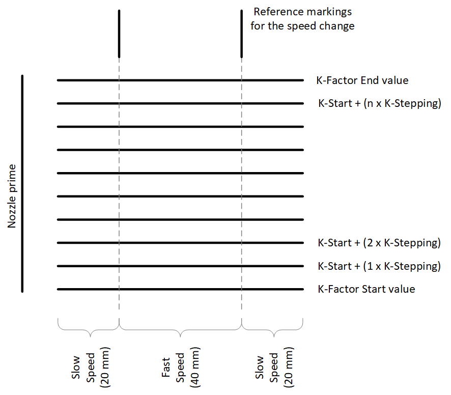
Beginning with the chosen Start value for K, individual lines will be printed from left to right. Each line consists of 20mm extrusion using Slow Printing Speed being followed by 40mm of Fast Printing Speed and finally being concluded by another 20mm of Slow Printing Speed.
For each new line the K-Factor will be increased by the K-Factor Stepping value, up to the provided End Value for K.
General considerations for the Test Pattern Settings
- Bowden extruders need a higher K-Factor than direct extruders. Consider a
Start value for Kof around 0.1 up to anEnd Value for Kof around 2.0 for LIN_ADVANCE v1.5 or around 30 up to anEnd Value for Kof around 130 for v1.0. - The best matching K-Factor to be used in production depends on.
- Type of filament. Extremely flexible filaments like Ninjaflex may not work at all.
- Printing temperature.
- Extruder characteristics: Bowden vs. direct extruder , Bowden length, free filament length in the extruder, etc.
- Nozzle size and geometry.
- The extruder’s steps/mm value has to be calibrated precisely. Calibration is recommended at low speeds to avoid additional influences.
- Minimize Backlash caused by gears geared extruder or by push fittings. As it will not influence the K-Factor, it can lead to strange noises from the extruder due to the pressure control.
Repeat the calibration, if any of the above parameters change.
Evaluating the Calibration Pattern
The transition between Slow Printing Speed phases and Fast Printing Speed phases are the points of interest to determine the best matching K-Factor. Following illustration shows a magnified view of a line where the K-Factor is too low:
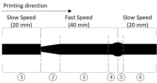
| Phase | Description |
|---|---|
| 1 | Slow Printing Speed |
| 2 | Beginning of the Fast Printing Speed. The pressure build up in the nozzle (= amount of extruded material) is lagging behind the acceleration of the print-head. This results in too little material and a starved line. Towards the end of this phase, the pressure is catching up to its intended value. |
| 3 | Extrusion and print-head movement are in sync. The nominal line width is extruded |
| 4 | Beginning of the deceleration towards Slow Printing Speed. Here the opposite of Phase 2 can be observed: The pressure decrease in the nozzle is lagging behind the deceleration of the print-head. This results in too much material being extruded |
| 5 | Beginning of the Slow Printing Speed phase. Still the pressure in the nozzle is not in sync with the intended extrusion amount and the line is suffering from over-extrusion. |
| 6 | Slow Printing Speed has stabilized. |
A too high K-Factor essentially reverses the above picture. The extruded amount will overshoot at the start of an acceleration and starve in the deceleration phase.
The test line, which has a fluid and barely visible or even invisible transition between the different speed phases represents the best matching K-Factor.
Setting the K-Factor for production
Considerations before using Linear Advance
- Some slicers have options to control the nozzle pressure. Common names are: Pressure advance, Coast at end, extra restart length after retract. Disable these options as they will interfere with Linear Advance.
- Also disable options like wipe while retract or combing. There should be almost no ooze, once the proper K-Factor is found.
- Recheck retraction distance, once Linear Advance is calibrated and working well. It may even be as low as 0, since pressure control reduces the material pressure at the end of a line to nearly zero.
The following considerations are no longer a problem with LIN_ADVANCE version 1.5
- This feature adds extra load to the CPU (and possibly more wear on the extruder). Using a communication speed of 115200 baud or lower to prevent communication errors and “weird” movements is recommended.
- The print host software should be using line numbers and checksums. (This is disabled by default, e.g., in Simplify3D)
- Theoretically there should be no “extra” movements produced by
LIN_ADVANCE. If extra movements were produced, this would tend to increase wear on more fragile parts such as the printed gears of a Wade extruder.
Saving the K-Factor in the Firmware
If only one filament material is used, the best way is to set the K-Factor inside Configuration_adv.h and reflash the firmware:
/**
 * Implementation of linear pressure control
 *
 * Assumption: advance = k * (delta velocity)
 * K=0 means advance disabled.
 * See Marlin documentation for calibration instructions.
 */
#define LIN_ADVANCE

#if ENABLED(LIN_ADVANCE)
#define LIN_ADVANCE_K <your_value_here>
Adding the K-Factor to the G-code Start Script
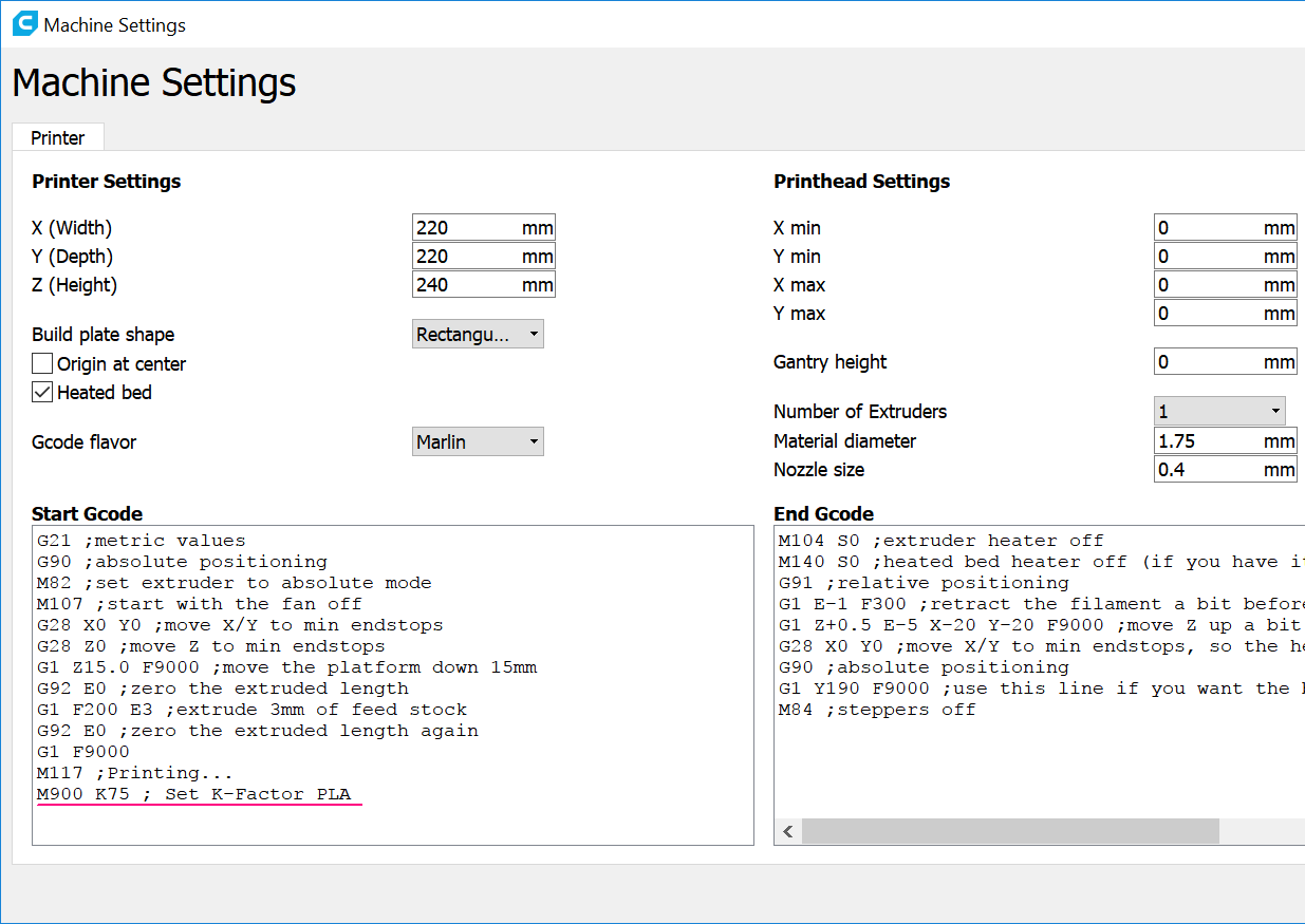
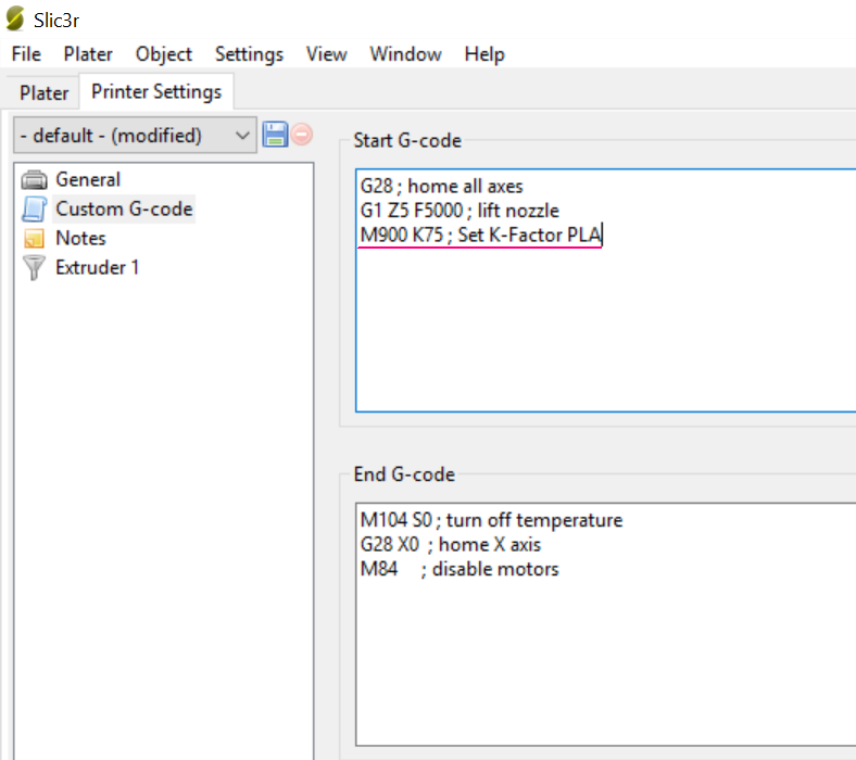
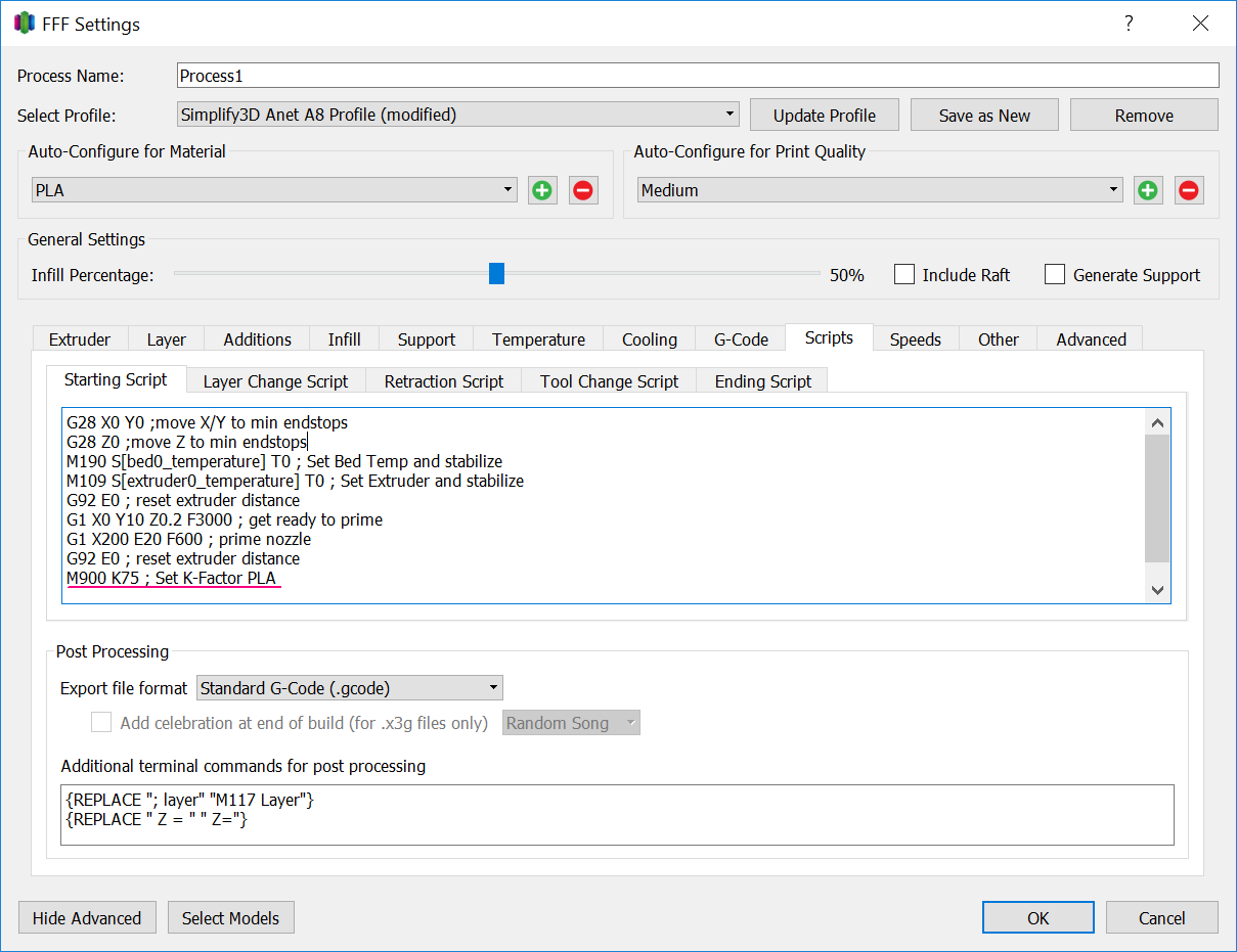
G-code Start Scripts are supported by various slicers. The big advantage of setting the K-Factor via this methods is that it can easily be modified, e.g., when switching to a different material. The K-Factor is defined by adding the command M900 Kxx to the end of the start script, where xx is the value determined with the above test pattern.
The following chapter briefly describes where to find the relevant setting in popular slicers.
Note 1:
With the G-code Start Script method, the feature still needs to be activated in the firmware as described in Saving the K-Factor in the Firmware. It is recommended to set #define LIN_ADVANCE_K to 0, which effectively disables the hard-coded firmware value. In this case only the K-Factor set via the start script is used.
Note 2:
The shown G-code Start Scripts are individual to each printer and personal taste. This is only intended to demonstrate where the K-Factor setting can be applied.
Cura
Settings —> Printer —> Manage Printer —> Machine Settings
Slic3r
Settings —> Printer Settings —> Custom G-code
Simplify 3D
Edit Process Settings —> Show Advanced –> Scripts —> Custom G-code
Developer Information
General Informations
The force required to push the filament through the nozzle aperture depends, in part, on the speed at which the material is being pushed into the nozzle. If the material is pushed faster (=printing fast), the filament needs to be compressed more before the pressure inside the nozzle is high enough to start extruding the material.
For a single, fast printed line, this results in under-extrusion at the line’s starting point (the filament gets compressed, but the pressure isn’t high enough) and over-extrusion with a blob at the end of the line (the filament is still compressed when the E motor stops, resulting in oozing).
For a complete print, this leads to bleeding edges at corners (corners are stop/end points of lines) and in extreme cases even gaps between perimeters due to under-extrusion at their starting points.
Version 1.5
Version 1.5 handles the pressure correction in a slightly different way to reach the following goals:
- respect extruder jerk
- ensure a smooth extruder movement without rattling
- reduce load inside stepper ISR
It does this by calculating an extruder speed offset within the planner for the given segment. If we have a true, linear acceleration then this will execute the needed advance steps just in time, so we have reached all our needed advance steps just when the acceleration part is over. As Marlin uses an approximation for the acceleration calculation inside the ISR, this is not perfectly true, we will come to this later. If the needed speed offset exceeds the allowed extruder jerk, the print acceleration for this segment is reduced to a lower value so extruder jerk is not exceeded any more. This is comparable to the check Marlin does for each axis, for example if we have a print acceleration of 2000mm/s² but X axis max. acceleration is set to 500mm/s², print acceleration is reduced to 500mm/s². During the trapezoid calculation, LIN_ADVANCE calculates the needed amount of advance steps at cruising speed and at final speed (=speed at and of the block).
When this block is executed by the stepper ISR, the extruder is set to a frequency which represents the calculated speed offset. The advance step is executed together with normal e steps. During the block runtime, the pressure will be advanced until the precalculated needed extra step amount is reached or the deceleration is started. During deceleration we reduce the advance step amount until we reach the amount for final speed or the block comes to an end. This checks are necessary as Marlin uses an approximation for acceleration calculation as mentioned above. Therefore, for example, we might not reach the final pressure at end of move perfectly but that’s not important as this error will not cumulate.
The next update might include improved handling of variable width moves. On variable width path it’s possible that we need to deplete pressure during acceleration, for example when the next line is much narrower than the previous one. Therefore LIN_ADVANCE would need to check for the actual extruder direction needed. Another case to be considered is the gap fill to the tip of a triangle: in this case Marlin will move on with a constant speed, but the extruder speed and therefore needed pressure gets smaller and smaller when we approach the tip of the triangle. We should adapt nozzle pressure with max. possible speed (extruder jerk speed) then. As gap fill is done at quite low speeds by most slicers, we have to decide if that extra load is worth the effect. On 32bit boards where calculation performance is most likely not a problem, it makes sense in any case.
Version 1.0
The LIN_ADVANCE pressure control handles this free filament length as a spring, where K is a spring constant. When the nozzle starts to print a line, it takes the extrusion speed as a reference. Additional to the needed extrusion length for a line segment, which is defined by the slicer, it calculates the needed extra compression of the filament to reach the needed nozzle pressure so that the extrusion length defined by the slicer is really extruded. This is done in every loop of the stepper ISR.
During deceleration, the filament compression is released again by the same formula: advance_steps = delta_extrusion_speed * K. During deceleration, delta_extrusion_speed is negative, thus the advance_steps values is negative which leads to a retract (or slowed) movement, relaxing the filament again.
The basic formula (advance_steps = delta_extrusion_speed * K) is the same as in the famous JKN pressure control, but with one important difference: JKN calculates the sum of all required advance extruder steps inside the planner loop and distributes them equally over every acceleration and deceleration stepper ISR loop. This leads to the wrong distribution of advance steps, resulting in an imperfect print result. LIN_ADVANCE calculates the extra steps on the fly in every stepper ISR loop, therefore applying the required steps precisely where needed.
For further details and graphs have a look into this presentation, slides 7-9.
In Marlin, all the work is done in the stepper.* and planner.* files. In the planner loop, LIN_ADVANCE checks whether a move needs pressure control. This applies only to print moves, not to travel moves and extruder-only moves (like retract and prime).
In the Stepper::isr method, LIN_ADVANCE calculates the number of extra steps needed to reach the required nozzle pressure. To avoid missing steps, it doesn’t execute them all at once, but distributes them over future calls to the interrupt service routine.
In v1.0 there is no check if the extruder acceleration, speed or jerk will exceed the limits set inside Configuration.h!