Laser/Spindle Configuration (2.0.9.x)
This document is based on Marlin 2.0.9.x
Laser features and other related options are enabled when LASER_FEATURE is defined in Configuration_adv.h.
If your spindle / laser accepts PWM signals for variable power levels enable the SPINDLE_LASER_USE_PWM option and define a SPINDLE_LASER_PWM_PIN. A hardware-enabled PWM pin will provide the best results. Otherwise the cutter will simply be turned on full for any non-zero value and off for zero.
Power Modes
The default operating state for LASER_FEATURE is Standard Mode. In Standard Mode the M3/M4/M5 commands wait synchronize the planner (causing a momentary stop) before changing the power. This mode is good enough for a spindle and is provided for backward compatibility. Standard Mode can be used in combination with LASER_SYNCHRONOUS_M106_M107 (described below), and can be used to cut or to provide Spindle Feature operations when it is active.
There are two inline modes, selected using M3/M4 with the I parameter. M3 I enables Continuous Inline Mode and M4 I selects Dynamic Inline Mode. These modes remain set M5 I returns to Standard Mode. In these modes, power set with the S parameter doesn’t take effect right away, but applies on the next G1/G2/G3/G5 move.
Dynamic Inline Mode
Since Dynamic Inline Mode is new to Marlin (Oct 2021) it should still be considered under development and experimental. Dynamic Inline Mode scales laser power to the stepper feedrate so that a consistent amount of laser energy is applied to the workpiece throughout moves, even as they accelerate and decelerate. (It is similar to GRBL 1.1f in M4 dynamic mode.) Stay tuned.
Inline Mode
Since Marlin 2.0.9.x you’ll get the best results using Inline Mode power control. Inline Mode applies power to a selected laser output pin defined by SPINDLE_LASER_PWM_PIN. This pin should be a hardware-enabled PWM output for optimal performance. If PWM hardware is available it is activated by defining SPINDLE_LASER_USE_PWM, providing a range of power levels. Without a PWM pin the cutter is simply turned on full for any non-zero value and off for zero. Power values are set when movement G-codes G1/G2/G3/G5 are processed with an S-Value parameter such as G1 X10 Y10 S100. The inline power value is stored in the planner blocks so that laser power can be perfectly synchronized with every move.
Motion Mode
The GCODE_MOTION_MODES option must be enabled for full compatibility with G-code generated by LaserGRBL and other laser / CNC software. This feature allows Marlin to process shorthand G-code moves that don’t start with a G# command.
Non-Inline Moves
While inline mode is active the M3/M4/M5 G-codes are still processed and will wait for planner synchronization; they are then queued for the next move unless LASER_POWER_SYNC is enabled. The LASER_POWER_SYNC option allows any M3/M4 G-code S-values to be enqueued, synced, and processed by the stepper ISR without pausing. Thus if no move is in progress the power is applied immediately.
Trapezoid Power
While inline mode is active the trapezoid feature LASER_POWER_TRAP can be enabled. The LASER_POWER_TRAP option allows the laser power to be compensate during acceleration or deceleration of a move. It helps to reduce laser burning hot spots. It is important to note that if this feature is enabled on CO2 based lasers it may require that the SPEED_POWER_MIN option value is set. CO2 Lasers typically do not activate at very low PWM values. This feature will use the SPEED_POWER_MIN to ensure the laser power will not be below the minimum power activation value. The value is determined by testing incremental power values until the CO2 Laser fires.
Laser on Fan Pin
In addition to inline mode we support laser synchronous fan mode set by defining LASER_SYNCHRONOUS_M106_M107. Laser synchronous fan mode uses G-codes M106/M107 to set laser power on a fan output pin. This feature sets the laser power using planner “sync” blocks, which allow power to be set in perfect sync with movement. This mode works well, however inline mode is faster when performing raster image-based laser burns.
Pins
Fan pin example
Define pin 5 as the second fan just add this line to Configuration.h:
#define FAN1_PIN 5 // 2nd fan output attached to laser TTL input
Example of G-code using M106 P1
M106 P1 S0   ; Laser off (P1 = 2nd fan output)
M106 P1 S128 ; Laser at 50%
M106 P1 S255 ; Laser at 100%
Inline pin example
Define pin 6 as the PWM pin and pin 4 as the ENABLE pin Configuration_adv.h.
These are the defaults for any RAMPS board and are already defined in pins_RAMPS.h. Override the default values by defining the desired values in Configuration_adv.h.
#define SPINDLE_LASER_PWM_PIN 6 // Hardware PWM laser TTL input
#define SPINDLE_LASER_ENA_PIN 4 // CO2 PSU enable input
Example of G-code using M3I:
M3 I S20       ; Enter Continuous Inline Mode and preload the next move power with S20
G1 X10 Y10     ; Move to X10 Y10 with S20 power
G1 X20 S50     ; Move to X20 with S50 power
M5             ; Kill the power and remain in Continuous Inline Mode (M5 or M5I always waits for last move to complete)
It’s fairly easy to select a pin for SPINDLE_LASER_ENA_PIN. Any unused digital pin with a 0 to 3.3V-5V logic level is sufficient.
It is highly recommended to connect an external 1k-10k pullup resistor to the SPINDLE_LASER_ENA_PIN. This prevents the spindle/laser from powering on briefly during power-up or when the controller is reset (which happens whenever you connect or disconnect from most controllers).
Picking the PWM pin can be tricky. There are only 15 hardware PWM pins on an ATmega2560. Some are used by the system interrupts so are unavailable. Others are usually hardwired in the controller to functions you can’t do without. Fans, servos, and some specialized functions all want to have a PWM pin. Usually you’ll end up picking a function you can do without, commenting that function out (or not enabling it) and assigning its pin number to the speed pin. PINS_DEBUGGING and M43 can be helpful to locate the best candidates.
For all CPUs the hardware PWMs on TIMER1 are not available. Marlin uses TIMER1 to generate interrupts and sets it up in such a way that the none of its PWMs can be used.
Servos also make hardware PWM(s) unavailable. In this case it’s only the “A” PWM that’s unavailable. The other hardware PWM(s) on that timer are available for general use.
ATmega2560 PWM Assignments and Clients
Below is a table that can be used when selecting the speed pin on a 2560. (Other CPUs include a subset of the 2560 pins.)
There are 16 PWM ports assigned to 15 physical pins.
Pin 13 has two ports assigned to it. (0A and 1C)
| Timer + Port | Digital Pin | Normal Assignment | System Use | Optional Clients |
| TIMER3B | 2 | X_MAX | ||
| TIMER3C | 3 | X_MIN | ||
| TIMER0B | 4 | HEATER_4 | ||
| TIMER3A | 5 | HEATER_5 | servo 0-11 ISR | |
| TIMER4A | 6 | HEATER_6 | servo 12-23 ISR | |
| TIMER4B | 7 | LCD | ||
| TIMER4C | 8 | HOTBED | ||
| TIMER2B | 9 | HEATER_1 | ||
| TIMER2A | 10 | HEATER_0 | ||
| TIMER1A | 11 | HEATER_7 | *stepper ISR | |
| TIMER1B | 12 | PS_ON_PIN | *stepper ISR | |
| TIMER0A | 13 | LED | LED PWM | |
| TIMER1C | 13 | *stepper ISR | ||
| TIMER5C | 44 | LCD | stepper motor current XY PWM | |
| TIMER5B | 45 | LCD | stepper motor current Z PWM | |
| TIMER5A | 46 | Z_STEP | stepper motor current E PWM or servo 24-35 ISR |
* These hardware PWMs are not available. The pin can still be used for general purpose digital I/O.
In addition to the above, fans can be assigned to PWM pins. If you pick a pin that’s already assigned to a fan then you’ll need to delete the fan or change its pin assignment. This is needed even if FAN_FAST_PWM is disabled.
NOTE: Most pins hardwired to a heater or fan are usually driven by a MOSFET with a pullup on its output through an LED to +12V/+24V. This will probably damage your spindle controller unless you add a protection circuit. If there isn’t a +12V/+24V pullup you’ll need an external 1k-10k pullup resistor to the pin.
AT90USB646, 647, 1286 & 1287 PWM assignments
- As with the atmega2560, the PWMs on Timer1 are not available.
- These chips have 10 PWMs assigned to 9 pins.
TIMER0AandTIMER1Care tied to the same pin. Most Arduino IDE extensions only makeTIMER1Cavailable (Teensyduino included).
ATmega644 & 1284 PWM assignments
- As with the 2560, the PWMs on Timer1 are not available.
- All PWMs have their own pins.
Other features
Serveral useful features are currently available for Lasers with 12864 LCDs and even 2004 LCDs:

Air Assist
Air Assist pump relay output, enables Menu item and G-code M8/M9 control.
  #define AIR_ASSIST                           // Air Assist control with G-codes M8-M9
  #if ENABLED(AIR_ASSIST)
    #define AIR_ASSIST_ACTIVE           LOW    // Active state on air assist pin
    #define AIR_ASSIST_PIN              44     // Override the default Air Assist pin
  #endif
Air Evacuation
Air Evacuation motor relay output, enables Menu item and G-code M10/M11 control.
  #define AIR_EVACUATION                       // Cutter Vacuum / Laser Blower motor control with G-codes M10-M11
  #if ENABLED(AIR_EVACUATION)
    #define AIR_EVACUATION_ACTIVE       LOW    // Set to "HIGH" if the on/off function is active HIGH
    #define AIR_EVACUATION_PIN          42     // Override the default Cutter Vacuum or Laser Blower pin
  #endif
Ammeter
Ammeter support, enables laser current monitoring on both 12864 & 2004 LCDs. This is a low side configuration (Ground) current IC that can be used for both CO2 and Diode based lasers. It’s ideal with High Voltage CO2 laser tubes, it connects between chassis ground and the tube ground. The current can be calibrated by measuring the current with an multimeter then adjusting the I2C_AMMETER_SHUNT_RESISTOR slightly up or down to match the measured value.
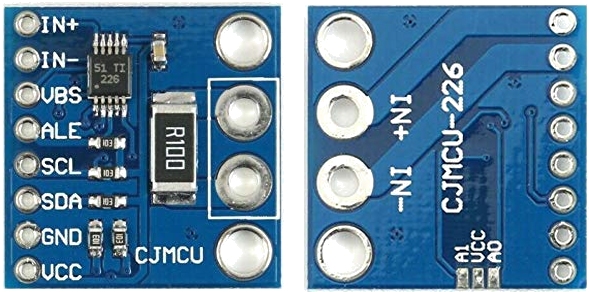
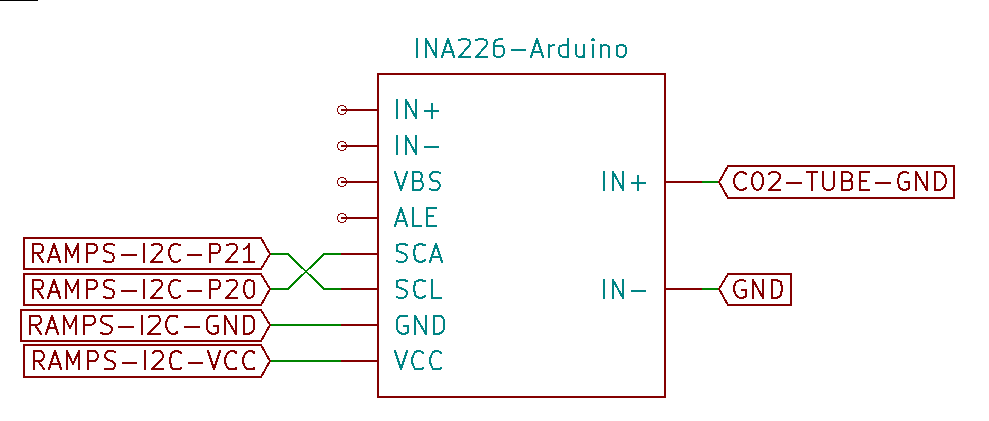
// Laser I2C Ammeter (High precision INA226 low/high side module)
#define I2C_AMMETER
#if ENABLED(I2C_AMMETER)
    #define I2C_AMMETER_IMAX            0.1    // (Amps) Calibration value for the expected current range
    #define I2C_AMMETER_SHUNT_RESISTOR  0.1    // (Ohms) Calibration shunt resistor value
#endif
Flow Meter
CO2 Coolant flow meter support, enables laser coolant monitoring on both 12864 & 2004 LCDs. Provides tube protection by detecting flow failures and controlling laser enable signals.
// Laser Coolant Flow Meter
#define LASER_COOLANT_FLOW_METER
#if ENABLED(LASER_COOLANT_FLOW_METER)
  #define FLOWMETER_PIN         20  // Requires an external interrupt-enabled pin (e.g., RAMPS 2,3,18,19,20,21)
  #define FLOWMETER_PPL       5880  // (pulses/liter) Flow meter pulses-per-liter on the input pin
  #define FLOWMETER_INTERVAL  1000  // (ms) Flow rate calculation interval in milliseconds
  #define FLOWMETER_SAFETY          // Prevent running the laser without the minimum flow rate set below
  #if ENABLED(FLOWMETER_SAFETY)
    #define FLOWMETER_MIN_LITERS_PER_MINUTE 1.5 // (liters/min) Minimum flow required when enabled
  #endif
#endif
Laser Cooler
Laser cooling control, provides chiller control with temperature monitoring and safety.
// Laser Cooler options
#if TEMP_SENSOR_COOLER
  #define COOLER_MINTEMP           8  // (°C)
  #define COOLER_MAXTEMP          26  // (°C)
  #define COOLER_DEFAULT_TEMP     16  // (°C)
  #define TEMP_COOLER_HYSTERESIS   1  // (°C) Temperature proximity considered "close enough" to the target
  #define COOLER_PIN               8  // Laser cooler on/off pin used to control power to the cooling element (e.g., TEC, External chiller via relay)
  #define COOLER_INVERTING     false
  #define TEMP_COOLER_PIN         15  // Laser/Cooler temperature sensor pin. ADC is required.
  #define COOLER_FAN                  // Enable a fan on the cooler, Fan# 0,1,2,3 etc.
  #define COOLER_FAN_INDEX         0  // FAN number 0, 1, 2 etc. e.g.
  #if ENABLED(COOLER_FAN)
    #define COOLER_FAN_BASE      100  // Base Cooler fan PWM (0-255); turns on when Cooler temperature is above the target
    #define COOLER_FAN_FACTOR     25  // PWM increase per °C above target
  #endif
#endif
Spindle Coolant
Spindle based coolant control, enables M7/M8/M9 G-codes.
#define COOLANT_CONTROL
#if ENABLED(COOLANT_CONTROL)
  #define COOLANT_MIST                // Enable if mist coolant is present (M7)
  #define COOLANT_FLOOD               // Enable if flood coolant is present (M8)
  #define COOLANT_MIST_INVERT  false  // Set "true" if the on/off function is reversed
  #define COOLANT_FLOOD_INVERT false  // Set "true" if the on/off function is reversed
#endif