Endstops
Endstops or limit switches are used on every moving axes of a 3D printer. The following chapter will provide information on:
- Purpose of the endstop
- Types of endstops
- Configuring endstops and probes
- Electromagnetic Interference / Electric Noise impact on endstops
Endstops purpose
Endstops fulfill two important functions in a 3D printer: Reference system for the axes system and safety.
Reference for the axes system
After powering up a 3D printer the printer’s controller board does not know at which position its axes are. Marlin indicates this by blinking question-marks in place of X, Y and Z on the LCD screen (v1.1.8 and older) or blinking ‘?’ in place of the coordinates besides X,Y and Z (Marlin v1.1.9 / v2.0.0 and newer).
This means the system needs first to establish its starting point of the physical (machine) coordinate system, a process called Homing. Homing can be initiated either via the G28 G-code or via the LCD controller.
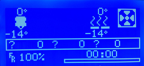
Figure 1: LCD indication not homed axes (Marlin <= v1.1.8)
Safety
The other important aspect of an endstop is protecting the hardware from damage. Should any movement try to exceed the physical limits of the machine, the endstop will cut the movement.
Types of endstops
There are two main types of endstops. Hardware endstops and software endstops.
Hardware endstops
Hardware endstops are electrically connected to the endstop ports of the printer control board and will provide a signal when the endstop condition is met.
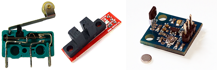
Figure 2: Most common endstops (left to right): Micro switch, optical endstop (light barrier), hall sensor (magnetic)
Regardless of the type the basic way of working is the same:
- A typically 5 Volt signal (HIGH) drops to 0 Volt (LOW): Normally closed (NC) switch
- A 0 Volt signal (LOW) rises to 5 Volts (HIGH): Normally open (NO) switch
Note
Since endstops are a safety feature NC switches are recommended as they will halt the machine should the switch be damaged, e.g. by a broken cable etc.
Probe as Z-Endstop
Probes can act like an endstop for the minimum Z-axis. While the typical endstop has a fixed position, the probe is mounted on the print-head and can freely move around the bed.
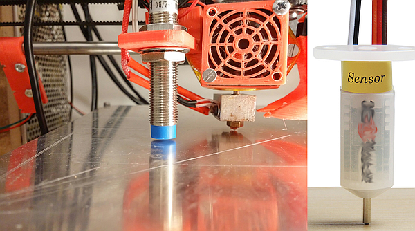
Figure 3: Common probe types: Inductive (left), solenoid touch probe (right)
Some aspects of probe configuration are considered in this endstop introduction. Further reading is provided in the Chapter Probes Configuration, Auto Bed Leveling and Unified Bed Leveling.
Software Endstops
Typically 3D printers are only equipped with hardware endstops on one side of each axis (Minimum or Maximum of the respective axis). As discussed above this is used to determine the starting point (origin) of the machine coordinate system.
In order to also protect the other side of the axes software endstops should be defined in the firmware via the #define MAX_SOFTWARE_ENDSTOPS / #define MIN_SOFTWARE_ENDSTOPS directive. This then uses the value from #define [XYZ]_MAX_POS / #define [XYZ]_MIN_POS to determine the maximum distance between the physical endstop and the software commanded stop of the axis. Software endstops can be (de-)activated via the M211 G-code.
Configuring endstops and probes.
Background
By default, slicers generate G-code that places the base of a printed model at z=0 and build upwards from there. The result of homing the z-axis should thus place the build surface at the z=0 plane. After homing in z, the hardware z endstop is deactivated (unless you have set ENDSTOPS_ALWAYS_ON_DEFAULT in Configuration_adv.h, which can be overridden by M120, M121), but to protect the hardware a software endstop is activated (which in turn can be overridden by M211 S0). This software endstop is located at Z_MIN_POS (defined in Configuration.h) . This is normally at z=0 at the nominal location of the bed. Note that when using bed-leveling, this software endstop is applied to the uncorrected slicer generated z-values. This allows printing into the hollows of the bed, where z < 0.
We now describe some common Cartesian printer configurations, with and without bed-leveling probes.
Microswitch endstop - no bed leveling probe.
Here we mechanically adjust the bed and possibly additionally the microswitch trigger point to level the bed surface as close as we can to the z=Z_MIN_POS (normally = 0) plane. The z location of the hardware (microswitch) trigger point defaults to the value of Z_MIN_POS. It is possible however to use a microswitch trigger point above the bed by setting MANUAL_Z_HOME_POS to the z-coordinate of the trigger point. See here. Having the trigger point below the bed makes little sense as the nozzle would crash into the bed before the microswitch triggered on homing.
Probe used for homing and bed-leveling.
The probe should be mounted so that its trigger point lies below the extruder nozzle. Z_PROBE_OFFSET_FROM_EXTRUDER (negative!) is this vertical offset. This offset is applied by the firmware when homing in order to properly reference the coordinate system to the nozzle position. To measure this see here. For a mechanical probe like a BL-Touch, this offset is geometrically fixed. For a remote sensing probe (e. g. inductive or capacitive), the offset might vary with bed material. You can tweak it using M851.
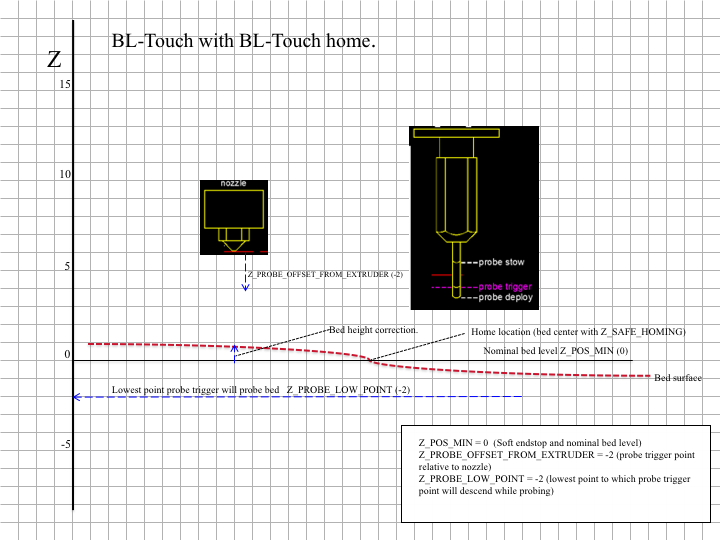
Figure 1: Example configuration using BL-Touch for both homing and probing.
The process of bed-leveling generates an array of z-values of the bed heights at the probed points. Marlin interpolates these values to estimate the bed height at any given x/y location. Figure 1 illustrates the situation. While probing, all endstops are turned off so that the probe can reach into the valleys of the bed. To protect the machine in case of the probe failure during probing set Z_PROBE_LOW_POINT to limit the probing depth.
Microswitch used for homing, probe for bed leveling.
When homing, the printer is not protected against hardware endstop failure. This configuration uses a perhaps more reliable microswitch for homing, reserving the probe for bed leveling, where Z_PROBE_LOW_POINT provides failure protection. The configuration is illustrated in Fig. 2, requiring the use of both MANUAL_Z_HOME_POS and Z_PROBE_OFFSET_FROM_EXTRUDER Ideally, with an uneven bed, MANUAL_Z_HOME_POS should be adjusted so that z=0 lies halfway between the highest and lowest parts of the bed. This makes the maximum bed correction as small as possible.
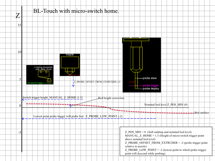
Figure 2: Example configuration using a microswitch for homing, BL-Touch for bed-leveling probe.
Measuring offsets.
To measure an offset between a trigger point and the bed, lower the nozzle to the trigger point (by homing, if it’s the homing device), and note the z-value. Now turn off the software endstop temporarily (with M211 S0) to enable lowering the nozzle further down to the bed. Note the z again. The difference is the height of the respective trigger point above the bed.
Endstops and Electromagnetic Interference (EMI)
Electromagnetic Interference (EMI) or electric noise, is an effect which can ruin the clean signal needed to properly and precisely measure electronically, be it temperature, endstop hits or any other value.
Sources and effect of EMI
In today’s life an abundance of sources for Electric Noise exists: Mobile phones, microwaves, WIFI, power supplies etc. There are also some prominent and strong sources of such noise in the 3D printer itself:
- Heated beds
- Hot ends
- Stepper motors
- PWM modulation
The Electromagnetic Interference created by these sources are picked up by other components, either because they are directly connected or via radiation. The useful signal needed by the other components will be disturbed or even altered so much that it is no longer useful.
Effect on endstops / limit switches
In the following HIGH = Logic 1 = 5 Volt will be used for a pressed switch and LOW = Logic 0 = 0 Volt for a not triggered switch.
Ideal endstop characteristic
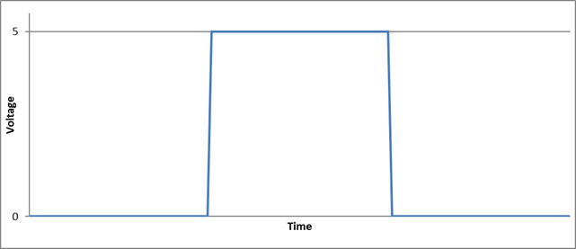
Figure 4: Ideal Endstop
The above Figure 4 shows an ideal endstop characteristic: Once pressed it jumps from LOW to HIGH and the printer control board realizes this in virtually no time.
Real endstop characteristic with low noise
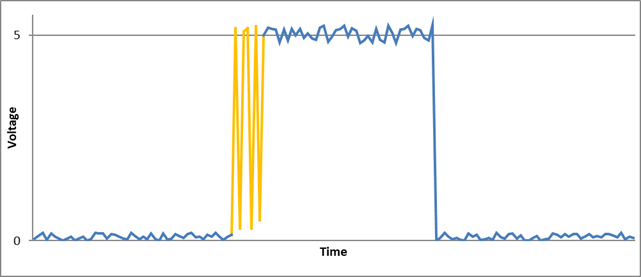
Figure 5: Real endstop characteristic
Figure 5 shows:
- There is no clean LOW or HIGH. Both states are somewhat unclean.
- Around the trigger point (marked in orange) a “bouncing” effect is shown: Due to mechanical influences the switch bounces between LOW and HIGH a few times before settling at HIGH.
- Bouncing is unwanted but in case of endstops not a show stopper
Real endstop characteristic with peak noise
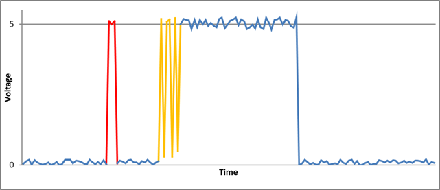
Figure 6: Real endstop with EMI
This Figure 6 shows:
- Same characteristic as above but with a peak caused by EMI (marked in red)
- The peak is high enough to be falsely detected by the printer control board as pressed switch, potentially ruining a running print
Countermeasures
There are numerous countermeasures you can take to reduce noise:
- Use shielded cables / twisted cable pairs
- Apply careful cable routing (i.e., keep signal cables far away from power cables)
- Enable software “debounce” filtering
- Add hardware filtering, such as a diode or capacitor
Options 3 and 4 are discussed further below.
Software Filtering
The code to deal with endstop noise is improved and exposed as a setting beginning in Marlin v1.1.9 and v2.0. In previous versions filtering is always active. To aid precision this is now exposed as a user setting in Configuration.h, deactivated by default.
/**
 * Endstop Noise Filter
 *
 * Enable this option if endstops falsely trigger due to noise.
 * NOTE: Enabling this feature means adds an error of +/-0.2mm, so homing
 * will end up at a slightly different position on each G28. This will also
 * reduce accuracy of some bed probes.
 * For mechanical switches, the better approach to reduce noise is to install
 * a 100 nanofarads ceramic capacitor in parallel with the switch, making it
 * essentially noise-proof without sacrificing accuracy.
 * This option also increases MCU load when endstops or the probe are enabled.
 * So this is not recommended. USE AT YOUR OWN RISK.
 * (This feature is not required for common micro-switches mounted on PCBs
 * based on the Makerbot design, since they already include the 100nF capacitor.)
 */
//#define ENDSTOP_NOISE_FILTER
Activating this option produces the following endstop characteristics:
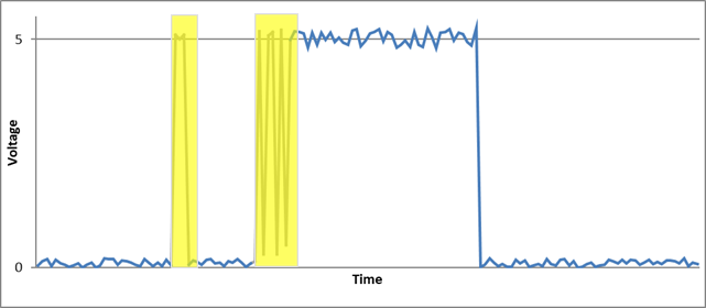
Figure 7: Endstop with software filtering
The area marked in yellow in Figure 7 shows where software compensation is active. The first yellow area is a noise effect where the algorithm decides no endstop is triggered since the signal falls back to a LOW state.
The second yellow area shows a real, desired endstop trigger. The algorithm “watches” the situation for a few milliseconds before deciding if the endstop is really triggered or if an EMI / Noise effect needs to be compensated. This leads to a delay and some loss of precision in endstop detection.
Note
Depending on the printer’s geometry and the affected endstop, loss of precision may result in issues such as inconsistent bed leveling, so this feature is not recommended. Instead, try to apply some kind of hardware filtering.
Hardware Filtering
Hardware filtering can range from an RC-unit (a simple capacitor in parallel to the switch over a resistor / capacitor combination) to opto-couplers and flip-flops.
Board
Some printer controller boards have built-in filters in the endstop connectors. Unfortunately the popular RAMPS v1.4 design does not, an oversight that’s been corrected with RAMPS v1.4.2:
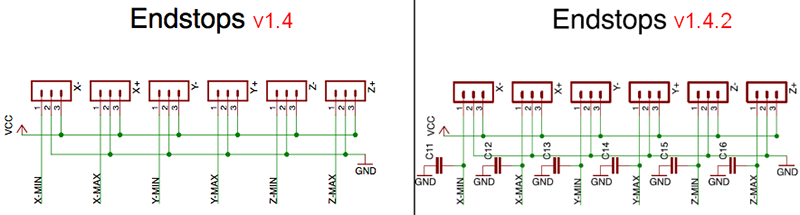
Figure 8: RAMPS v1.4 vs v1.4.2
Endstop PCB
For 3D printing ready made filtered endstops are available, e.g. according to the Makerbot design:
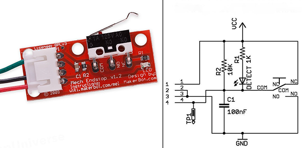
Figure 9: Endstop PCB with RC unit
Endstop with capacitor
A simpler variant –easily fitted to endstops– is a 100nF capacitor, soldered over the two endstop connector pins (in parallel):
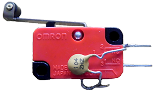
Figure 10: Endstop with 100nF capacitor
The Effect of Hardware Filtering
Figure 11 below shows the effect of hardware filtering: The noise level is smoothed and peaks are reduced so much that they no longer cause false readings. And the fast-bouncing signal at the initial trigger is dampened.
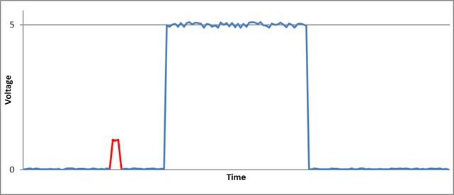
Figure 11: Endstop characteristic with hardware filter
Conclusion
Never underestimate electrical noise. It may be invisible but it can lead to strange and spurious effects that are tricky to diagnose. Simple measures (like adding a capacitor) will improve the situation a lot, improving the overall reliability of the machine.