Unified Bed Leveling
The Unified Bed Leveling (UBL) system is a superset of the previous leveling systems.
The main improvements over the previous systems are:
- Optimized line-splitting algorithm. For all mesh-based leveling methods, on Cartesians each linear move is split on grid line boundaries, respecting the best-known measured heights on the bed. UBL highly optimizes this boundary-splitting with pre-calculation, optimized handling of special cases, and avoiding recursion.
- It is possible to probe and store a high-resolution rectangular mesh in nonvolatile storage, load this mesh, and use either 3-point or grid based probing to ‘tilt’ the mesh and compensate for slight changes in bed orientation.
- The user is able to fill in the portions of the mesh that can’t be reached by automated probing. This allows the entire bed to be compensated.
- It allows the user to fine tune the system. The user is able to modify the mesh based on print results. Really good first layer adhesion and height can be achieved over the entire bed.
Synopsis
Currently an LCD display with a rotary encoder is recommended. Note that the MKS TFT 2.8 and 3.2 do not actually fulfill the LCD requirements. The main documentation below assumes that a conforming LCD and a Z-probe are present. See the no-lcd addendum for information on using UBL without a display, and the no-Z-probe addendum to get UBL working without a Z-probe installed. Note that operation without an LCD is still work-in-progress, and subject to change.
UBL is a superset of previous automatic leveling systems, but it does not necessarily supersede them in all cases. Its goal is to allow the best features of the previous leveling schemes to be used together and combined, as well as providing a richer set of commands and feedback for the user. However, this functionality comes at a cost of program space. Compared to bilinear leveling, for example, the difference might be 50 kB for UBL vs. 5 kB for bilinear – and for an equally precise mesh the printed results could be quite similar. With that said, the cost in program space is likely only a concern for more resource constrained parts like the 128k ATMegas.
The printer must be already fully functional and tested, with a well-constrained movement system. The more physically level and straight the bed is, the better your results will be. See Configuration.h and Configuration_adv.h for all of UBL’s settings.
You should be able to successfully print a small object at the center of the bed with bed leveling turned off. It’s very important to verify that your Configuration.h settings make this possible before trying to bring up UBL. Most problems bringing up the UBL Bed Leveling system occur when this step has been ignored. Please pay particular attention to your Z_PROBE_OFFSET_FROM_EXTRUDER value. Usually it’s best to home the Z-Axis in the center of the bed. But wherever you decide to home, the Z value reported on the LCD (or with M114) should be very close to 0.0 mm when the nozzle is just touching the bed. Failure to calibrate Z_PROBE_OFFSET_FROM_EXTRUDER properly will result in dimensional errors in your printed parts.
The following command sequences can then be used as a quick-start guide to home, level, and fine-tune the results. These commands are for a ‘normal’ setup; see the relevant addenda for concerns and G-code sequences related to setups without an LCD or Z-probe.
Setup and Initial Probing
M190 S65        ; Set bed temp to 65C (S65) recommended for accuracy when using a heated bed
M104 S210       ; Set nozzle temp to 210C (S210) recommended for accuracy when using nozzle to probe

G28             ; Home XYZ.
G29 P1          ; Do automated probing of the bed.
G29 P2 B T      ; Manual probing of locations. (USUALLY NOT NEEDED!)
G29 P3 T        ; Repeat until all mesh points are filled in.

G29 T           ; View the Z compensation values.
G29 S0          ; Save UBL mesh points to slot 0.
G29 F 10.0      ; Set Fade Height for correction at 10.0 mm.
G29 A           ; Activate the UBL System.
M500            ; Save settings to EEPROM.
                ; WARNING: Causes UBL to be active at power-up, before any G28.
Mesh Fine-Tuning
G26 C P5.0 F3.0 ; Produce mesh validation pattern (G26), continue with closest point (C), prime nozzle by extruding 5mm (P5.0), and set filament diameter 3mm (F3.0)
                ; PLA temperatures are assumed unless you specify, e.g., B105 H225 for ABS Plastic
G29 P4 T        ; Move nozzle to 'bad' areas and fine tune the values if needed
                ; Repeat G26 and 'G29 P4 T' commands as needed.

G29 S0          ; Save UBL mesh values to slot 0.
M500            ; Save settings to EEPROM.
Transform Mesh with 3-Point Probing
G29 L0          ; Load UBL mesh values from slot 0.
G29 J           ; Probe 3 points and tilt the mesh to the plane.
                ; This can be useful in the starting G-code of your preferred slicer.
Scope
The UBL system contains a suite of tools with multiple options intended to cover almost any situation. This document is aimed at getting a new user acquainted with the most used tools and options needed to produce a high quality print.
The intent is to provide a new user with enough knowledge of the UBL system that they can go to the detailed documentation and start working with the other tools and options as needed.
The 3-point leveling option is only covered to the extent of using it to transform an already-measured mesh.
Theory
UBL projects a rectangular grid over the print bed. A Z height is measured at each point (confluence) in the grid.
Linear moves are split at grid boundaries. For each segment the Z offset at start and end are calculated. The Z compensation varies linearly from the start to end of the move.
Note that kinematic systems like Delta and SCARA already split moves into very small segments, removing the need to split moves at grid boundaries. In the future, moves may be split into smaller segments on Cartesian also to produce more fine-grained Z height changes through the move.
The Z compensation on any grid line is the simple linear interpolation of the Z offsets of the two corners it connects.
The Z compensation for any point within a grid box is produced by calculating the bilinear interpolation of the Z offsets of the four corner points. See the addendum Bilinear computation for details.
Tools are provided that can populate the Z compensation values at the mesh points via automated probing, manual probing, and manually entering a value. The intent of UBL is to allow the entire printable area of the bed to have usable Z compensation values.
The initial auto bed leveling procedure rarely produces great results across the whole bed. Fine editing tools are used to tune the mesh more finely. UBL includes a test print utility to aid in the tuning process.
Process overview
To create a mesh that produces good first-layer results over the entire bed, follow this procedure:
- Setup the UBL parameters in
Configuration.handConfiguration_adv.h. - Perform automated probing.
- Perform additional manual probing, if needed.
- Fill in un-probed points in the mesh
- Run the test print utility.
- Fine tune the matrix.
- Repeat steps 5 and 6 until satisfied.
An LCD controller with rotary encoder, while not required, substantially simplifies the process.
The printer (and LCD) must be fully functional before starting this process.
UBL Configuration
UBL configuration options are located in Configuration.h and Configuration_adv.h.
Enable these options:
-
AUTO_BED_LEVELING_UBL. Leave the others commented out. -
G26_MESH_VALIDATIONto enable theG26test print utility. -
EEPROM_SETTINGS. EEPROM support is required. - One of the LCD options. An LCD with a rotary encoder is strongly recommended.
Z Probe XY offsets should be set to within 1mm of the measured distance from the nozzle to the probe. Ideally the error should be less than +-2mm. Errors of 5mm have been known to cause difficulties in fine-tuning.
Travel limits & bed size tell the system where the nozzle can reach. This is used during automated probing to determine what points the PROBE can reach.
All printers require these settings, which specify the physical movement limits for the nozzle:
// The size of the print bed
#define X_BED_SIZE xxx
#define Y_BED_SIZE xxx

// Travel limits (mm) after homing, corresponding to endstop positions.
#define X_MIN_POS xxx
#define Y_MIN_POS xxx
#define Z_MIN_POS xxx
#define X_MAX_POS xxx
#define Y_MAX_POS xxx
#define Z_MAX_POS xxx
Mesh size and density – These define the default boundaries of the UBL mesh - the region of the bed the nozzle(s) can reach, and therefore needs to be compensated - and the mesh density. These settings can be found in Configuration.h.
Ideally the mesh bounds will match your printable area perfectly. In practice it’s a good idea to pull these in a bit with MESH_INSET if the printable area goes right up to the edge of the bed. This helps keep the probe from missing the bed.
3 x 3 through 15 x 15 meshes are supported. X & Y dimensions do NOT need to be the same. First time users should start out with a small mesh until they are familiar with the tools. Once you’re proficient then move to larger meshes. 7 x 7 seems to be a popular size for a first attempt at a final mesh.
#define MESH_INSET 10             // Mesh inset margin on print area
#define GRID_MAX_POINTS_X 3       // Don't use more than 15 points per axis, implementation limited.
#define GRID_MAX_POINTS_Y GRID_MAX_POINTS_X
The automated mesh boundary settings assume that the printable area is centered in the physical bed area (as specified below), and just applies an inset to all sides. If your configuration is different then you may need to modify the min/max settings, found in Configuration_adv.h, to fit your situation. Note though that (unlike bilinear leveling) the MESH_MIN_* and MESH_MAX_* positions refer to where the nozzle can reach, not the probe.:
#define MESH_MIN_X UBL_MESH_INSET
#define MESH_MAX_X (X_BED_SIZE - (UBL_MESH_INSET))
#define MESH_MIN_Y UBL_MESH_INSET
#define MESH_MAX_Y (Y_BED_SIZE - (UBL_MESH_INSET))
For delta printers the situation is similar. It is necessary to have grid points defined that can be filled covering the entirety of DELTA_PRINTABLE_RADIUS, but there should also be a ‘border’ of valid mesh points that lie just outside the printable radius. This ensures that every grid cell within the printable radius will have all four of its corners defined.
So however bed size and printable radius are defined, make sure that your mesh grid is defined so that a full circle of ‘extra’ mesh points lie outside of the printable radius.
3-point probe positions - If you plan to use 3-point probing to ‘touch up’ the orientation of a saved mesh then you will also need to make sure that the 3-point leveling probe points are all accessible by your probe.
Marlin 1.x
#define UBL_PROBE_PT_1_X 39       // Probing points for 3-Point leveling of the mesh
#define UBL_PROBE_PT_1_Y 180
#define UBL_PROBE_PT_2_X 39
#define UBL_PROBE_PT_2_Y 20
#define UBL_PROBE_PT_3_X 180
#define UBL_PROBE_PT_3_Y 20
Marlin 2.x
#define PROBE_PT_1_X 15
#define PROBE_PT_1_Y 180
#define PROBE_PT_2_X 15
#define PROBE_PT_2_Y 20
#define PROBE_PT_3_X 170
#define PROBE_PT_3_Y 20
Commands
UBL has a series of “phase” commands that roughly follow the mesh building process. Some are heavily used, some aren’t.
There are several options that can be applied to each of the phase commands. These are the most common:
| Command | Description |
|---|---|
G29 P1 | Phase 1 – Automatically probe the bed. |
G29 P2 | Phase 2 – Manually probe points that automated probing couldn’t reach. |
G29 P3 | Phase 3 – Extrapolate values for points that automated probing couldn’t reach. |
G29 P4 | Phase 4 – Manually fine tune the mesh. |
G29 Snn | Store the mesh in EEPROM slot nn. |
G29 Lnn or M420 Lnn | Load a mesh from EEPROM slot nn. (Other leveling systems use M501.) |
G29 A or M420 S1 | Activate UBL Z compensation bed leveling. |
G29 D or M420 S0 | Disable UBL Z compensation bed leveling. |
G29 T or M420 V | Print a map of the mesh to console. |
G26 | Print a pattern to test mesh accuracy. |
M421 | Touch up mesh points by specifying a value (Z) or offset (Q). |
M502 | Restore all settings to factory defaults. |
M500 | Save settings to EEPROM. |
Automated probing
The first step in the process is to use the Z probe to populate as much of the mesh as possible.
To start the process issue G29 P1 or, if you want to see the values as they are measured, G29 P1 T
If the EEPROM hasn’t been initialized then it’ll tell you to issue the M502, M500, M501 sequence. If that happens then you’ll need to re-issue the G29 P1 command.
If a G28 hasn’t already been done then the G28 sequence will automatically be done followed by the G29 P1 probing.
No further action is required of the user for this phase.
If you do a G29 T or M420 V command you’ll most likely see areas that do not have Z compensation values. See the addendum Mesh area for details.
Manual probing
This optional step uses the encoder wheel to move the nozzle up and down in 0.01mm steps. BE VERY CAREFUL when doing this. Nasty things can happen if too much force is applied to the bed by the nozzle.
Most systems will have areas that the Z probe can’t reach. These points can be manually probed using G29 P2, but the ‘smart’ mesh filling of G29 P3 is often good enough to make manual probing unnecessary.
Manual probing consists of lowering the nozzle until the nozzle comes in contact with a feeler gauge. Usually the feeler gauge is a piece of paper or a business card. It’s better if the gauge is a piece of plastic that’s hard but still has some flex. Even better is a mechanic’s metal feeler gauge but those are usually too short to be convenient.
The idea is to stop lowering when there is the first sign of resistance to moving the gauge. It is very important to be consistent in the amount of force/resistance from point to point.
The first step is to measure the thickness of the feeler gauge:
-
Issue
G29 P2 B Tto start. -
The nozzle will move to the center of the bed.
-
Use the encoder wheel to move the nozzle until you feel a small amount of resistance. This is the resistance level you’ll want to aim for when manually probing.
-
Click the encoder button.
-
Remove the feeler gauge.
-
Lower the nozzle VERY SLOWLY until the nozzle just touches the bed.
-
Click the encoder button.
-
The nozzle will move to the first unmeasured location. Use the encoder to lower the nozzle until the desired resistance is felt with the feeler gauge. Click the encoder. The nozzle then moves to the next unmeasured location. Repeat until all locations are measured.
-
See the host interface screen for the grid position you’re currently probing.
When done, you can use G29 S to save the mesh to EEPROM.
Filling in the mesh
UBL includes a third phase, G29 P3, which fills in points on the mesh that were not probed automatically or manually. Note that unlike in bilinear leveling, UBL does not automatically extrapolate correction beyond the bounds of the mesh. If a mesh point is not defined no correction will be applied, and a missing point can affect up to 4 mesh cells.
Issue G29 P3 (no other parameters) to do a ‘smart fill’ of missing mesh points. This uses an extrapolation algorithm - which varies between delta and Cartesian systems - to give the unfilled mesh points reasonable initial values. You may need to run this more than once – each instance of G29 P3 will fill in one missing line of the grid. This allows fine tuning between P3 steps when filling the remainder of larger grids. From this point, G26 and G29 P4 can be used to iteratively refine the mesh.
G29 P3 Cx.xx can be used to manually fill a value into a mesh point(s), like M421, if for some reason that is necessary. G29 P3 Cx.xx Rn will fill the nearest n points with the value x.xx; ‘nearest’ is referenced to the nozzle position, unless X and Y arguments are provided to override the search start point.
Again, G29 S[n] will save the mesh to EEPROM.
Test print
Once you have a reasonable looking mesh then it’s time to do a test print.
The easiest way to do this is to use the G26 command. There are several options for the G26 command. (See G26 for full details.)
G26 Bxx Hyy F1.75 L0.2 S0.4 will usually get you something reasonable:
-
Bxx– bed temperature -
Hyy– hotend temperature -
F1.75– filament width of 1.75mm (default) -
L0.2– layer height of 0.2mm (default) -
S0.4– nozzle diameter of 0.4mm (default)
Mesh Fine-tuning
Look over the results of the G26 print and note where adjustments are needed.
To edit a single point move the nozzle close to the point that needs adjustment. Issue a G29 P4 T. The head will move to nearest point. Use the encoder wheel to change the value. If UBL_MESH_EDIT_MOVES_Z is enabled in Configuration.h (the default setting) the nozzle will change height during this process. If it is disabled the nozzle will not move.
The values in the mesh indicate how far the nozzle needs to move along the Z axis to compensate for imperfections in the bed. Positive values mean that the nozzle needs to move away from the bed (“up”) and negative values mean that the nozzle needs to move towards the bed (“down”). Thus, if the G26 print shows that for a specific mesh point the nozzle is too close to the bed (the lines are “squished” or the nozzle hit the bed when printing the test pattern) the value of the mesh point should be increased. If the nozzle is too far away from the bed (lines are too thin or not even sticking to the bed) the value of the mesh point should be decreased. This may cause the mesh point value to change from positive to negative or vice versa.
For example, suppose that a mesh point has a probed value of -0.022 and the test pattern shows that the nozzle is too close at that point. If an adjustment of +0.050 is desired (moving the nozzle 0.050mm away from the bed) the new value for the mesh point would be +0.028.
If UBL_MESH_EDIT_MOVES_Z is enabled it is also possible to use a piece of paper or a feeler gauge to adjust the position. Use a command of the form G29 P4 Hxxx where xxx is the thickness of the feeler gauge (or piece of paper) being used to adjust the nozzle height. For example G29 P4 H0.1 is a good option to use with a piece of paper.
To edit multiple points move the nozzle close to the first point and issue G29 P4 T Rxx where xx is the number of points you want to edit. You can look at the host interface screen to see where in the grid you are currently editing.
Press and hold the encoder button/wheel when you are finished.
There are options (G29 P4 X... Y...) to make it easier to move to the desired probe locations. For example G29 P4 X110 Y110 will move to the grid point closest to the center of a 220x220mm bed.
It’s probably a good idea to issue a G29 S command to save the mesh to EEPROM at this stage.
Repeat the G26, G29 P4 T sequence until you have the desired first layer height quality.
Issue a G29 S command periodically to save your mesh.
As you print parts you may notice that further fine-tuning is needed. The G29 P4 T command can be used anytime to make adjustments.
Addenda
UBL without an LCD
If you don’t have an LCD with encoder, or you have something like a MKS TFT that doesn’t behave like a proper display, then you will need to modify this process slightly.
First, it is especially important that you physically level the bed as well as possible prior to initially probing the bed with G29 P1. This is always a prerequisite, but it is especially important here because without an LCD there’s no easy way to abort the probe process if the nozzle starts getting too close to the bed.
Possible workarounds are to keep your finger on the reset button/power switch so you can quickly stop the probe process, or being ready to quickly issue M112 (emergency stop) if and only if you have EMERGENCY_PARSER enabled in Configuration_adv.h.
The same cautions apply to using the G26 test print command; if something goes wrong you want a way to quickly abort the process before your print head is driven into the bed.
G29 P2 (manual probe) is not available without a functional LCD, so instead of the sequence above users should skip directly from G29 P1 (auto-probe) to G29 P3 (smart fill). Likewise, G29 P4 R... cannot be used to interactively edit the mesh, so M421 must be used instead to manually adjust individual mesh points. With UBL, the M421 Q form can be used to offset the specified mesh point, avoiding the need to specify absolute values.
In summary, initial set-up without an LCD might look like this:
G29 P1          ; Automatically probe accessible area
G29 P3          ; Fill un-probed areas with reasonable values - may need to be repeated
G26             ; Start test print / validation process
M421 ... Qx.xx  ; Direct edit mesh point, using offset
G29 S1          ; Save to slot 1, return to G26 for further refinement.
UBL without a Z-probe
UBL also includes the features previously provided by MESH_BED_LEVELING and PROBE_MANUALLY, allowing the user to take advantage of the system without having a Z-probe at all. Again, the initialization and start-up process needs to be varied a bit.
As in the case of no LCD, it is important to have good physical leveling of the bed before you start here - especially if you try to skip the manual probing step.
In this case instead of starting with G29 P1 to automatically probe the bed, you want to start with G29 P0 to zero the mesh. From here you can go straight to the cycle of G26... to print a test pattern and G29 P4 R... to fine-tune mesh points - probably working your way ‘down’ from the worst area(s) of the validation pattern, and using G29 S to save results between iterations. You can also use G29 P2 to manually probe first, which is recommended.
If you use G29 P2 to probe manually first, you probably want to at least probe the center and four corners of the bed – possibly some points in between as well. Then you want to use G29 P3 commands to fill in reasonable initial values for the rest of the mesh before moving on to the G26 / G29 P4 cycle. G29 P3 Rn Cx.xx will fill in the nearest n grid points (to the nozzle) with the value specified by Cx.xx. You will probably have to use the G29 P3 C... form initially, rather than trying to let the smart fill algorithm handle lots of undefined points.
So in summary, initial set-up of a mesh might look like this:
G29 P0      ; Zero the mesh
; Optional
G29 P2...   ; Probe manually at appropriate locations
G29 P3...   ; Fill in missing points
; /Optional
G26         ; Jump into validation print / edit process
G29 P4 R... ; Refine mesh points
G29 S1      ; Save to slot 1, return to G26 for further refinement
Bilinear computation
- Uses the Z heights at the 4 corners of the current XY position’s grid box.
- Performs a bilinear interpolation of the Z heights:
- Calculates Z height (z1) at the left edge of the box for the current Y by linear interpolation.
- Calculates Z height (z2) at the right edge of the box for the current Y by linear interpolation.
- Calculates Z height at the current X by linear interpolation between z1 and z2. This is the Z offset used for the move.
MESH areas
After G29 P1 your matrix will probably have areas that do not have Z compensation values. This is because the probe can’t be positioned in these areas. The only ways to avoid this are:
- Use the nozzle as the probe (no offsets).
- Build your system so that the nozzle can travel outside the bed.
If your probe is in front and to the right of your nozzle then the matrix will look like one of these.
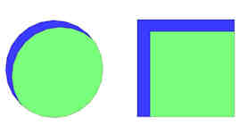
- GREEN: Probing is possible
- BLUE: Probe can’t reach
Further Optimization
Going forward, we’ve been thinking anew about boundary-splitting and delta-style line-splitting. On kinematic systems, moves are split into small segments, so the nozzle already closely follows the (bilinear approx.) curve of the bed on those machines. Thus, on kinematic systems we can theoretically skip the boundary-splitting step.
At the same time, we also realize that for mesh-based bed leveling, splitting up lines into smaller segments has extra benefit for Cartesians too. So, if we simply enable move-splitting for cartesians when mesh leveling is enabled, we can skip boundary-splitting while also improving leveling accuracy. Since it requires some extra computation, this ought to be an optional feature.
More Information
- See also G26 Mesh Validation and G29 for UBL.