Configuring Marlin
Marlin has many features and options. They are defined and documented in two very large files:
-
Configuration.hcontains the core settings for the hardware, language and controller selection, and settings for the most common features and components. -
Configuration_adv.hcontains more detailed customization options, add-ons, experimental features, and other esoteric settings.
Build-time configuration options describe aspects of the machine that will never change, such as the total build area. Other settings define defaults that can be changed while the printer is running, such as the preheat temperatures.
Marlin also provides minimal and intelligent configuration methods that may be more suitable for your needs. Give these a try and let us know what you think!
-
Config.h(2.1.3 and up) should contain just your pertinent settings. This replacesConfiguration.handConfiguration_adv.h, which will be ignored. -
config.ini(2.1.0 and up) modifies the configuration files at the start of a PlatformIO build and has some other useful powers. See the Configuration with INI page to see if it’s right for you.
Compiler Directives
Marlin is configured using C #define statements so the firmware can be as small, fast, and efficient as possible, but if you want all the bells and whistles and your board has the power, you can go for it.
Settings are enabled, disabled, and assigned values using C preprocessor syntax like so:
#define THIS_IS_ENABLED    // this switch is enabled
//#define THIS_IS_DISABLED // this switch is disabled
#define OPTION_VALUE 22    // this setting is "22"
Migration
To use configurations from an earlier version of Marlin, first try dropping them into the newer Marlin, updating CONFIGURATION_H_VERSION and CONFIGURATION_ADV_H_VERSION, and building the firmware. As part of the build process, Marlin will check for outdated options and show error messages that explain exactly what needs to be changed.
To migrate your settings to a new Configuration you can use tools like Notepad++ or Winmerge to compare old configurations with the newer (default) configurations and copy settings over on a change-by-change basis. Most settings will come over without changes, then you can review any tricky changes that remain.
Sources of Documentation
The most authoritative source on configuration details will always be the configuration files themselves. They provide pretty complete descriptions of each option, and are themselves the source for most of the information presented here.
It’s hard to know as a beginner which settings are important and which can be safely ignored.
Here are some useful resources to get you started configuring and calibrating your 3D Printer:
- Marlin Example Configurations
- “Marlin Firmware Help” YouTube Playlist
- Marlin Daily Builds
- Triffid Hunter’s Calibration Guide
- Calibrating Steps-per-unit (video)
- Calibration of your RepRap
Before You Begin
For the main settings you’ll need to know a few things about your machine:
- Printer style, such as Cartesian, Delta, CoreXY, or SCARA
- Driver board, such as RAMPS, RUMBA, Teensy, etc.
- Number of extruders
- Steps-per-mm for XYZ axes and extruders (can be tuned later)
- Endstop positions
- Thermistors and/or thermocouples
- Probes and probing settings
- LCD controller brand and model
- Add-ons and custom components
Configuration.h
The most fundamental settings for your hardware are found here.
This section follows the order of settings as they appear. The order isn’t always logical, so “Search In Page” may be helpful. We’ve tried to keep descriptions brief and to the point. For more detailed information on various topics, please read the main articles and follow the links provided in the option descriptions.
Configuration versioning
#define CONFIGURATION_H_VERSION 02010300
Marlin now checks for a configuration version and won’t compile without this setting. If you want to upgrade from an earlier version of Marlin, add this line to your old configuration file and set it to the current version. During the build Marlin will throw errors explaining what needs to be changed.
Firmware Info
#define STRING_CONFIG_H_AUTHOR "(none, default config)"
//#define CUSTOM_VERSION_FILE Version.h
-
STRING_CONFIG_H_AUTHORis shown in the Marlin startup message to identify the author (and optional variant) of the firmware. Use this setting as a way to uniquely identify your custom configurations. The startup message is printed whenever the board (re)boots. -
CUSTOM_VERSION_FILEcan be set to the name of a custom firmware version file. SeeMarlin/Version.hfor the standard version file.
Hardware Info
Motherboard
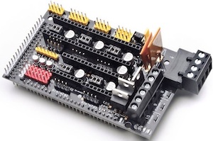
#define MOTHERBOARD BOARD_RAMPS_14_EFB
The most important setting is Marlin is the motherboard. The firmware needs to know what board it will be running on so it can assign the right functions to all pins and take advantage of the full capabilities of the board. Setting this incorrectly will lead to unpredictable results.
Using boards.h as a reference, replace BOARD_RAMPS_14_EFB with your board’s ID. The boards.h file has the most up-to-date listing of supported boards - check there first if you don’t see yours listed here.
Serial Port
#define SERIAL_PORT 0
The index of the on-board serial port that will be used for primary host communication. Change this if, for example, you need to connect a wireless adapter to non-default port pins.
The first serial port (-1 or 0) will always be used by the Arduino bootloader regardless of this setting.
#define SERIAL_PORT_2 -1
Enable this if your board has a secondary serial port.
Serial port -1 is the USB emulated serial port, if available.
Baud Rate
#define BAUDRATE 115200
The serial communication speed of the printer should be as fast as it can manage without generating errors. In most cases 115200 gives a good balance between speed and stability. Start with 250000 and only go lower if “line number” and “checksum” errors start to appear. Note that some boards (e.g., a temperamental Sanguinololu clone based on the ATMEGA1284P) may not be able to handle a baud rate over 57600. Allowed values: 2400, 9600, 19200, 38400, 57600, 115200, 250000.
Bluetooth
#define BLUETOOTH
Enable the Bluetooth serial interface. For boards based on the AT90USB.
Custom Machine Name
//#define CUSTOM_MACHINE_NAME "3D Printer"
This is the name of your printer as displayed on the LCD and by M115. For example, if you set this to “My Delta” the LCD will display “My Delta ready” when the printer starts up.
Configurable Machine Name
//#define CONFIGURABLE_MACHINE_NAME
Add G-code M550 to set/report the Machine Name. Enable this option if you need to be able to change the Machine Name for lab use or to switch host configs. Available in Marlin 2.1.3.
Machine UUID
//#define MACHINE_UUID "00000000-0000-0000-0000-000000000000"
A unique ID for your 3D printer. A suitable unique ID can be generated randomly at uuidtools.com. Some host programs and slicers may use this identifier to differentiate between specific machines on your network.
Stepper Drivers
#define X_DRIVER_TYPE  A4988
#define Y_DRIVER_TYPE  A4988
#define Z_DRIVER_TYPE  A4988
//#define X2_DRIVER_TYPE A4988
//#define Y2_DRIVER_TYPE A4988
//#define Z2_DRIVER_TYPE A4988
//#define Z3_DRIVER_TYPE A4988
//#define Z4_DRIVER_TYPE A4988
//#define I_DRIVER_TYPE  A4988
//#define J_DRIVER_TYPE  A4988
//#define K_DRIVER_TYPE  A4988
//#define U_DRIVER_TYPE  A4988
//#define V_DRIVER_TYPE  A4988
//#define W_DRIVER_TYPE  A4988
#define E0_DRIVER_TYPE A4988
//#define E1_DRIVER_TYPE A4988
//#define E2_DRIVER_TYPE A4988
//#define E3_DRIVER_TYPE A4988
//#define E4_DRIVER_TYPE A4988
//#define E5_DRIVER_TYPE A4988
//#define E6_DRIVER_TYPE A4988
//#define E7_DRIVER_TYPE A4988
These settings allow Marlin to tune stepper driver timing and enable advanced options for stepper drivers that support them. You may also override timing options in Configuration_adv.h. Each driver is associated with an axis (internal axis identifiers: X, Y, Z, I, J, K, U, V, W) or an extruder (E0 to E7).
Each axis gets its own stepper control and endstops depending on the following settings:
Steppers: *_STEP_PIN, *_ENABLE_PIN, *_DIR_PIN, *_ENABLE_ON Endstops: *_STOP_PIN, USE_*MIN_PLUG, USE_*MAX_PLUG Axes: *_MIN_POS, *_MAX_POS, INVERT_*_DIR Planner: DEFAULT_AXIS_STEPS_PER_UNIT, DEFAULT_MAX_FEEDRATE, DEFAULT_MAX_ACCELERATION, AXIS_RELATIVE_MODES, MICROSTEP_MODES, MANUAL_FEEDRATE
For multi-axis-machines (option I_DRIVER_TYPE … enabled), more information can be found at https://github.com/DerAndere1/Marlin/wiki.
Use TMC2208/TMC2208_STANDALONE for TMC2225 drivers and TMC2209/TMC2209_STANDALONE for TMC2226 drivers.
Additional Axis Settings
#ifdef I_DRIVER_TYPE
  #define AXIS4_NAME 'A' // :['A', 'B', 'C', 'U', 'V', 'W']
  #define AXIS4_ROTATES
#endif
#ifdef J_DRIVER_TYPE
  #define AXIS5_NAME 'B' // :['B', 'C', 'U', 'V', 'W']
  #define AXIS5_ROTATES
#endif
#ifdef K_DRIVER_TYPE
  #define AXIS6_NAME 'C' // :['C', 'U', 'V', 'W']
  #define AXIS6_ROTATES
#endif
#ifdef U_DRIVER_TYPE
  #define AXIS7_NAME 'U' // :['U', 'V', 'W']
  //#define AXIS7_ROTATES
#endif
#ifdef V_DRIVER_TYPE
  #define AXIS8_NAME 'V' // :['V', 'W']
  //#define AXIS8_ROTATES
#endif
#ifdef W_DRIVER_TYPE
  #define AXIS9_NAME 'W' // :['W']
  //#define AXIS9_ROTATES
#endif
Define AXISn_ROTATES for all axes that rotate or pivot. Rotational axis coordinates are expressed in degrees.
AXISn_NAME defines the letter used to refer to the axis in (most) G-code commands. By convention the names and roles are typically:
- ‘A’ : Rotational axis parallel to X
- ‘B’ : Rotational axis parallel to Y
- ‘C’ : Rotational axis parallel to Z
- ‘U’ : Secondary linear axis parallel to X
- ‘V’ : Secondary linear axis parallel to Y
- ‘W’ : Secondary linear axis parallel to Z
Regardless of these settings the axes are internally named I, J, K, U, V, W.
Extruder Info
Extruders
#define EXTRUDERS 1
This value, from 0 to 6, defines how many extruders (or E steppers) the printer has. By default Marlin will assume separate nozzles all moving together on a single carriage. If you have a single nozzle, a switching extruder, a mixing extruder, or dual X carriages, specify that below.
This value should be set to the total number of E stepper motors on the machine, even if there’s only a single nozzle.
Filament Diameter
#define DEFAULT_NOMINAL_FILAMENT_DIA 3.00
This is the “nominal” filament diameter as written on the filament spool (1.75, 2.85, 3.0). If you typically use 1.75mm filament, but physically measure the diameter as 1.70mm, you should still use 1.75 if that’s what you have set in your slicer.
This value is used by Marlin to compensate for Filament Width when printing in volumetric mode (See M200), and by the Unified Bed Leveling command G26 when printing a test grid.
You can override this value with M404 W.
Single Nozzle
#define SINGLENOZZLE
Enable SINGLENOZZLE if you have an E3D Cyclops or any other “multi-extruder” system that shares a single nozzle. In a single-nozzle setup, only one filament drive is engaged at a time, and each needs to retract before the next filament can be loaded and begin purging and extruding.
Průša MK2 Single Nozzle Multi-Material Multiplexer
//#define MK2_MULTIPLEXER
Enabling MK2_MULTIPLEXER allows one stepper driver on a control board to drive two to eight stepper motors, one at a time.
//#define E_MUX0_PIN 40  // Always Required
//#define E_MUX1_PIN 42  // Needed for 3 to 8 inputs
//#define E_MUX2_PIN 44  // Needed for 5 to 8 inputs
Override the default DIO selector pins.
Průša MMU2
#define PRUSA_MMU2
Enable support for the Průša Multi-material unit 2. This requires a free serial port on your printer board. To use the MMU2 you also have to
- enable NOZZLE_PARK_FEATURE
- set EXTRUDERS = 5
All details are configured in [Configuration_adv.h]
Switching Extruder
//#define SWITCHING_EXTRUDER
#if ENABLED(SWITCHING_EXTRUDER)
  #define SWITCHING_EXTRUDER_SERVO_NR 0
  #define SWITCHING_EXTRUDER_SERVO_ANGLES { 0, 90 } // Angles for E0, E1[, E2, E3]
  #if EXTRUDERS > 3
    #define SWITCHING_EXTRUDER_E23_SERVO_NR 1
  #endif
#endif
A Switching Extruder is a dual extruder that uses a single stepper motor to drive two filaments, but only one at a time. The servo is used to switch the side of the extruder that will drive the filament. The E motor also reverses direction for the second filament. Set the servo sub-settings above according to your particular extruder’s setup instructions.
Switching Nozzle
//#define SWITCHING_NOZZLE
#if ENABLED(SWITCHING_NOZZLE)
  #define SWITCHING_NOZZLE_SERVO_NR 0
  //#define SWITCHING_NOZZLE_E1_SERVO_NR 1          // If two servos are used, the index of the second
  #define SWITCHING_NOZZLE_SERVO_ANGLES { 0, 90 }   // Angles for E0, E1 (single servo) or lowered/raised (dual servo)
#endif
A Switching Nozzle is a carriage with 2 nozzles. A servo is used to move one of the nozzles up and down. The servo either lowers the active nozzle or raises the inactive one. Set the servo sub-settings above according to your particular extruder’s setup instructions.
Parking extruder (with solenoid)
//#define PARKING_EXTRUDER
Two separate X-carriages with extruders that connect to a moving part via a solenoid docking mechanism. Requires SOL1_PIN and SOL2_PIN.
Parking extruder (with magnets)
//#define MAGNETIC_PARKING_EXTRUDER
Two separate X-carriages with extruders that connect to a moving part via a magnetic docking mechanism using movements and no solenoid
#if EITHER(PARKING_EXTRUDER, MAGNETIC_PARKING_EXTRUDER)

  #define PARKING_EXTRUDER_PARKING_X { -78, 184 }     // X positions for parking the extruders
  #define PARKING_EXTRUDER_GRAB_DISTANCE 1            // (mm) Distance to move beyond the parking point to grab the extruder
  //#define MANUAL_SOLENOID_CONTROL                   // Manual control of docking solenoids with M380 S / M381

  #if ENABLED(PARKING_EXTRUDER)

    #define PARKING_EXTRUDER_SOLENOIDS_INVERT           // If enabled, the solenoid is NOT magnetized with applied voltage
    #define PARKING_EXTRUDER_SOLENOIDS_PINS_ACTIVE LOW  // LOW or HIGH pin signal energizes the coil
    #define PARKING_EXTRUDER_SOLENOIDS_DELAY 250        // (ms) Delay for magnetic field. No delay if 0 or not defined.
    //#define MANUAL_SOLENOID_CONTROL                   // Manual control of docking solenoids with M380 S / M381

  #elif ENABLED(MAGNETIC_PARKING_EXTRUDER)

    #define MPE_FAST_SPEED      9000      // (mm/m) Speed for travel before last distance point
    #define MPE_SLOW_SPEED      4500      // (mm/m) Speed for last distance travel to park and couple
    #define MPE_TRAVEL_DISTANCE   10      // (mm) Last distance point
    #define MPE_COMPENSATION       0      // Offset Compensation -1 , 0 , 1 (multiplier) only for coupling

  #endif

#endif
Adjust the relevant settings to your specifications for use with either PARKING_EXTRUDER or MAGNETIC_PARKING_EXTRUDER.
Switching Toolhead
//#define SWITCHING_TOOLHEAD
Support for swappable and dockable toolheads, such as the E3D Tool Changer. Toolheads are locked with a servo.
Magnetic Switching Toolhead
//#define MAGNETIC_SWITCHING_TOOLHEAD
Support swappable and dockable toolheads with a magnetic docking mechanism using movement and no servo.
Electromagnetic Switching Toolhead
//#define ELECTROMAGNETIC_SWITCHING_TOOLHEAD
For CoreXY / HBot kinematics, toolheads are parked at one edge and held with an electromagnet. Supports more than 2 toolheads. See https://youtu.be/JolbsAKTKf4
#if ANY(SWITCHING_TOOLHEAD, MAGNETIC_SWITCHING_TOOLHEAD, ELECTROMAGNETIC_SWITCHING_TOOLHEAD)
  #define SWITCHING_TOOLHEAD_Y_POS          235         // (mm) Y position of the toolhead dock
  #define SWITCHING_TOOLHEAD_Y_SECURITY      10         // (mm) Security distance Y axis
  #define SWITCHING_TOOLHEAD_Y_CLEAR         60         // (mm) Minimum distance from dock for unobstructed X axis
  #define SWITCHING_TOOLHEAD_X_POS          { 215, 0 }  // (mm) X positions for parking the extruders
  #if ENABLED(SWITCHING_TOOLHEAD)
    #define SWITCHING_TOOLHEAD_SERVO_NR       2         // Index of the servo connector
    #define SWITCHING_TOOLHEAD_SERVO_ANGLES { 0, 180 }  // (degrees) Angles for Lock, Unlock
  #elif ENABLED(MAGNETIC_SWITCHING_TOOLHEAD)
    #define SWITCHING_TOOLHEAD_Y_RELEASE      5         // (mm) Security distance Y axis
    #define SWITCHING_TOOLHEAD_X_SECURITY   { 90, 150 } // (mm) Security distance X axis (T0,T1)
    //#define PRIME_BEFORE_REMOVE                       // Prime the nozzle before release from the dock
    #if ENABLED(PRIME_BEFORE_REMOVE)
      #define SWITCHING_TOOLHEAD_PRIME_MM           20  // (mm)   Extruder prime length
      #define SWITCHING_TOOLHEAD_RETRACT_MM         10  // (mm)   Retract after priming length
      #define SWITCHING_TOOLHEAD_PRIME_FEEDRATE    300  // (mm/m) Extruder prime feedrate
      #define SWITCHING_TOOLHEAD_RETRACT_FEEDRATE 2400  // (mm/m) Extruder retract feedrate
    #endif
  #elif ENABLED(ELECTROMAGNETIC_SWITCHING_TOOLHEAD)
    #define SWITCHING_TOOLHEAD_Z_HOP          2         // (mm) Z raise for switching
  #endif
#endif
Adjust the relevant settings to your specifications for use with SWITCHING_TOOLHEAD, PARKING_EXTRUDER or MAGNETIC_PARKING_EXTRUDER.
Mixing Extruder
//#define MIXING_EXTRUDER
#if ENABLED(MIXING_EXTRUDER)
  #define MIXING_STEPPERS 2        // Number of steppers in your mixing extruder
  #define MIXING_VIRTUAL_TOOLS 16  // Use the Virtual Tool method with M163 and M164
  //#define DIRECT_MIXING_IN_G1    // Allow ABCDHI mix factors in G1 movement commands
#endif
A Mixing Extruder uses two or more stepper motors to drive multiple filaments into a mixing chamber, with the mixed filaments extruded from a single nozzle. This option adds the ability to set a mixture, to save mixtures, and to recall mixtures using the T command. The extruder still uses a single E axis, while the current mixture is used to determine the proportion of each filament to use. An “experimental” G1 direct mixing option is included.
MIXING_EXTRUDER enables M163 - set mix factor, M164 - save mix, and M165 - set mix.
Hotend Offsets
//#define HOTEND_OFFSET_X { 0.0, 20.00 } // (mm) relative X-offset for each nozzle
//#define HOTEND_OFFSET_Y { 0.0, 5.00 }  // (mm) relative Y-offset for each nozzle
//#define HOTEND_OFFSET_Z { 0.0, 0.00 }  // (mm) relative Z-offset for each nozzle
Hotend offsets are needed if your extruder has more than one nozzle. These values specify the offset from the first nozzle to each nozzle. So the first element is always set to 0.0. The next element corresponds to the next nozzle, and so on. Add more offsets if you have 3 or more nozzles.
Power Supply
//#define PSU_CONTROL
//#define PSU_NAME "Power Supply"

#if ENABLED(PSU_CONTROL)
  #define PSU_ACTIVE_HIGH false // Set 'false' for ATX (1), 'true' for X-Box (2)

  //#define PS_DEFAULT_OFF      // Keep power off until enabled directly with M80

  //#define AUTO_POWER_CONTROL  // Enable automatic control of the PS_ON pin
  #if ENABLED(AUTO_POWER_CONTROL)
    #define AUTO_POWER_FANS           // Turn on PSU if fans need power
    #define AUTO_POWER_E_FANS
    #define AUTO_POWER_CONTROLLERFAN
    #define AUTO_POWER_CHAMBER_FAN
    //#define AUTO_POWER_E_TEMP        50 // (°C) Turn on PSU over this temperature
    //#define AUTO_POWER_CHAMBER_TEMP  30 // (°C) Turn on PSU over this temperature
    #define POWER_TIMEOUT 30
  #endif
#endif
This option allows the controller board to switch the power supply 12V on and off with M80 and M81. Requires PS_ON_PIN.
//#define PS_DEFAULT_OFF
Enable this if you don’t want the power supply to switch on when you turn on the printer. This is for printers that have dual power supplies. For instance some setups have separate power supplies for heaters. In this situation you can save power by leaving the power supply off until needed.
Thermal Settings
Temperature Sensors

#define TEMP_SENSOR_0 1
#define TEMP_SENSOR_1 0
#define TEMP_SENSOR_2 0
#define TEMP_SENSOR_3 0
#define TEMP_SENSOR_4 0
#define TEMP_SENSOR_5 0
#define TEMP_SENSOR_6 0
#define TEMP_SENSOR_7 0
#define TEMP_SENSOR_BED 1
#define TEMP_SENSOR_PROBE 0
#define TEMP_SENSOR_CHAMBER 0
#define TEMP_SENSOR_COOLER 0
#define TEMP_SENSOR_BOARD 0
#define TEMP_SENSOR_SOC 0
#define TEMP_SENSOR_REDUNDANT 0
Reliable temperature sensors are important for your 3D printer to control heat, both for consistent material temperature and for fire safety. Select the appropriate thermistor or thermocouple from the list of available options. Match your sensor by brand/model; if none fits, use a “similar” one or use the generic profile 1. Accurate selection is essential for proper calibration!
The first set of options pertain to hotends. Up to 8 hotend sensors are supported in Marlin 2.1.x.
Set the Bed, Probe, Chamber, Cooler, and Board sensors according to your manufacturer’s guidance.
The SOC (System On Chip) sensor should be set to 100 (SoC internal sensor) when it exists. It requires a pin named ATEMP or TEMP_SOC_PIN to be defined.
The “redundant” temperature sensor can improve accuracy for one of the monitored temperatures. See the additional redundant temperature sensor settings below.
// Dummy thermistor constant temperature readings, for use with 998 and 999
#define DUMMY_THERMISTOR_998_VALUE  25
#define DUMMY_THERMISTOR_999_VALUE 100
Marlin provides two dummy sensors for testing purposes. Set their constant temperature readings here.
//#define TEMP_SENSOR_1_AS_REDUNDANT
#define MAX_REDUNDANT_TEMP_SENSOR_DIFF 10
Enable this option to use sensor 1 as a redundant sensor for sensor 0. This is an advanced way to protect against temp sensor failure. If the temperature difference between sensors exceeds MAX_REDUNDANT_TEMP_SENSOR_DIFF Marlin will abort the print and disable the heater.
Temperature Stability
#if HAS_E_TEMP_SENSOR
  #define TEMP_RESIDENCY_TIME         10  // (seconds) Time to wait for hotend to "settle" in M109
  #define TEMP_WINDOW                  1  // (°C) Temperature proximity for the "temperature reached" timer
  #define TEMP_HYSTERESIS              3  // (°C) Temperature proximity considered "close enough" to the target
#endif
Extruders must maintain a stable temperature for TEMP_RESIDENCY_TIME before M109 will return success and start the print. Tune what “stable” means using TEMP_HYSTERESIS and TEMP_WINDOW.
#if TEMP_SENSOR_BED
  #define TEMP_BED_RESIDENCY_TIME     10  // (seconds) Time to wait for bed to "settle" in M190
  #define TEMP_BED_WINDOW              1  // (°C) Temperature proximity for the "temperature reached" timer
  #define TEMP_BED_HYSTERESIS          3  // (°C) Temperature proximity considered "close enough" to the target
#endif
The bed must maintain a stable temperature for TEMP_BED_RESIDENCY_TIME before M109 will return success and start the print. Tune what “stable” means using TEMP_BED_HYSTERESIS and TEMP_BED_WINDOW.
#if TEMP_SENSOR_CHAMBER
  #define TEMP_CHAMBER_RESIDENCY_TIME 10  // (seconds) Time to wait for chamber to "settle" in M191
  #define TEMP_CHAMBER_WINDOW          1  // (°C) Temperature proximity for the "temperature reached" timer
  #define TEMP_CHAMBER_HYSTERESIS      3  // (°C) Temperature proximity considered "close enough" to the target
#endif
Redundant Temperature Sensor
#if TEMP_SENSOR_REDUNDANT
  #define TEMP_SENSOR_REDUNDANT_SOURCE    E1  // The sensor that will provide the redundant reading.
  #define TEMP_SENSOR_REDUNDANT_TARGET    E0  // The sensor that we are providing a redundant reading for.
  #define TEMP_SENSOR_REDUNDANT_MAX_DIFF  10  // (°C) Temperature difference that will trigger a print abort.
#endif
Use a temp sensor as a redundant sensor for another reading. Select an unused temperature sensor, and another sensor you’d like it to be redundant for. If the two thermistors differ by TEMP_SENSOR_REDUNDANT_MAX_DIFF (°C), the print will be aborted. Whichever sensor is selected will have its normal functions disabled; i.e., selecting the Bed Sensor (-1) will disable bed heating/monitoring.
For selecting source/target use: COOLER, PROBE, BOARD, CHAMBER, BED, E0, E1, E2, E3, E4, E5, E6, E7
Temperature Ranges
#define HEATER_0_MINTEMP 5
#define HEATER_1_MINTEMP 5
#define HEATER_2_MINTEMP 5
#define HEATER_3_MINTEMP 5
#define HEATER_4_MINTEMP 5
#define BED_MINTEMP 5
These parameters help prevent the printer from overheating and catching fire. Temperature sensors report abnormally low values when they fail or become disconnected. Set these to the lowest value (in degrees C) that the machine is likely to experience. Indoor temperatures range from 10C-40C, but a value of 0 might be appropriate for an unheated workshop.
If any sensor goes below the minimum temperature set here, Marlin will shut down the printer with a “MINTEMP” error.
Err: MINTEMP: This error means your thermistor has disconnected or become an open circuit. (Or the machine is just very cold.)
#define HEATER_0_MAXTEMP 285
#define HEATER_1_MAXTEMP 275
#define HEATER_2_MAXTEMP 275
#define HEATER_3_MAXTEMP 275
#define HEATER_4_MAXTEMP 275
#define BED_MAXTEMP      130
Maximum temperature for each temperature sensor. If Marlin reads a temperature above these values, it will immediately shut down for safety reasons. For the E3D V6 hotend, many use 285 as a maximum value.
Err: MAXTEMP: This error usually means that the temperature sensor wires are shorted together. It may also indicate an issue with the heater MOSFET or relay that is causing it to stay on.
Remember that cold surfaces near hot surfaces can lead to condensation, which is NOT GOOD for electronics. Use blower fans to keep air moving and use a Dew Point Calculator to check your local dew point.
PID
Marlin uses PID (Proportional, Integral, Derivative) control (Wikipedia) to stabilize the dynamic heating system for the hotends and bed. When PID values are set correctly, heaters reach their target temperatures faster, maintain temperature better, and experience less wear over time.
Most vitally, correct PID settings will prevent excessive overshoot, which is a safety hazard. During PID calibration, use the highest target temperature you intend to use (where overshoots are more critical).
See the PID Tuning topic on the RepRap wiki for detailed instructions on M303 auto-tuning. The PID settings should be tuned whenever changing a hotend, temperature sensor, heating element, board, power supply voltage (12/24V), or anything else related to the high-voltage circuitry.
Hotend PID Options
#define PIDTEMP
#define BANG_MAX 255     // limits current to nozzle while in bang-bang mode; 255=full current
#define PID_MAX BANG_MAX // limits current to nozzle while PID is active (see PID_FUNCTIONAL_RANGE below); 255=full current
#define K1 0.95
Disable PIDTEMP to run extruders in bang-bang mode. Bang-bang is a pure binary mode - the heater is either fully-on or fully-off for a long period. PID control uses higher frequency PWM and (in most cases) is superior for maintaining a stable temperature.
#if ENABLED(PIDTEMP)
  //#define PID_EDIT_MENU
  //#define PID_AUTOTUNE_MENU
  //#define PID_PARAMS_PER_HOTEND

  //#define PID_DEBUG
  //#define PID_OPENLOOP 1
  //#define SLOW_PWM_HEATERS
  #define PID_FUNCTIONAL_RANGE 10
Enable PID_AUTOTUNE_MENU to add an option on the LCD to run an Autotune cycle and automatically apply the result. Enable PID_PARAMS_PER_HOTEND if you have more than one extruder and they are different models.
PID Values
  #if ENABLED(PID_PARAMS_PER_HOTEND)
    // Specify between 1 and HOTENDS values per array.
    // If fewer than EXTRUDER values are provided, the last element will be repeated.
    #define DEFAULT_KP_LIST {  22.20,  22.20 }
    #define DEFAULT_KI_LIST {   1.08,   1.08 }
    #define DEFAULT_KD_LIST { 114.00, 114.00 }
  #else
    #define DEFAULT_KP  22.20
    #define DEFAULT_KI   1.08
    #define DEFAULT_KD 114.00
  #endif
Sample PID values are included for reference, but they won’t apply to most setups. The PID values you get from M303 may be very different, but will be better for your specific machine.
Bed PID Options
//#define PIDTEMPBED
Enable PIDTEMPBED to use PID for the bed heater (at the same PWM frequency as the extruders). With the default PID_dT the PWM frequency is 7.689 Hz, fine for driving a square wave into a resistive load without significant impact on FET heating. This also works fine on a Fotek SSR-10DA Solid State Relay into a 250 W heater. If your configuration is significantly different than this and you don’t understand the issues involved, you probably shouldn’t use bed PID until it’s verified that your hardware works. Use M303 E-1 to tune the bed PID for this option.
//#define BED_LIMIT_SWITCHING
Enable BED_LIMIT_SWITCHING
#define MAX_BED_POWER 255
The max power delivered to the bed. All forms of bed control obey this (PID, bang-bang, bang-bang with hysteresis). Setting this to anything other than 255 enables a form of PWM. As with PIDTEMPBED, don’t enable this unless your bed hardware is ok with PWM.
Bed PID Values
#if ENABLED(PIDTEMPBED)

  //#define PID_BED_DEBUG // Sends debug data to the serial port.

  // 120V 250W silicone heater into 4mm borosilicate (MendelMax 1.5+)
  // from FOPDT model - kp=.39 Tp=405 Tdead=66, Tc set to 79.2, aggressive factor of .15 (vs .1, 1, 10)
  #define  DEFAULT_BED_KP 10.00
  #define  DEFAULT_BED_KI .023
  #define  DEFAULT_BED_KD 305.4

  // 120V 250W silicone heater into 4mm borosilicate (MendelMax 1.5+)
  // from pidautotune
  //#define  DEFAULT_BED_KP 97.1
  //#define  DEFAULT_BED_KI 1.41
  //#define  DEFAULT_BED_KD 1675.16

  // FIND YOUR OWN: "M303 E-1 C8 S90" to run autotune on the bed at 90 degreesC for 8 cycles.
#endif // PIDTEMPBED
Sample Bed PID values are included for reference, but use the result from M303 E-1 for your specific machine.
Safety
Prevent Cold Extrusion

#define PREVENT_COLD_EXTRUSION
#define EXTRUDE_MINTEMP 170
“Cold Extrusion” refers to any movement of the extruder before the nozzle is hot enough to melt the filament. This could damage your extruder or hotend, but it usually just results in gouged filament and/or a jammed extruder. Keep this option enabled to disable extruder motion until the hotend is at or above the specified temperature. Override this setting with M302 if needed.
Prevent Lengthy Extrude
#define PREVENT_LENGTHY_EXTRUDE
#define EXTRUDE_MAXLENGTH 200
A lengthy extrusion may not damage your machine, but it could result in wasting costly filament. This feature is meant to prevent a typo or glitch in a G1 command from extruding some enormous amount of filament. For Bowden setups, the max length should be set greater than or equal to the load/eject length.
Thermal Protection
#define THERMAL_PROTECTION_HOTENDS // Enable thermal protection for all extruders
#define THERMAL_PROTECTION_BED     // Enable thermal protection for the heated bed
#define THERMAL_PROTECTION_CHAMBER // Enable thermal protection for the heated chamber
Thermal protection is one of the most vital safety features in Marlin, allowing the firmware to catch a bad situation and shut down heaters before it goes too far. Consider what happens when a thermistor comes loose during printing. The firmware sees a low temperature reading so it keeps the heat on. As long as the temperature reading is low, the hotend will continue to heat up indefinitely, leading to smoke, oozing, a ruined print, and possibly even fire.
Marlin offers two levels of thermal protection:
- Check that the temperature is actually increasing when a heater is on. If the temperature fails to rise enough within a certain time period (by default, 2 degrees in 20 seconds), the machine will shut down with a “
Heating failed” error. This will detect a disconnected, loose, or mis-configured thermistor, or a disconnected heater. - Monitor thermal stability. If the measured temperature drifts too far from the target temperature for too long, the machine will shut down with a “
Thermal runaway” error. This error may indicate poor contact between thermistor and hot end, poor PID tuning, or a cold environment.
More thermal protection options are located in Configuration_adv.h. In most setups these can be left unchanged, but should be tuned as needed to prevent false positives.
Information
For false thermal runaways not caused by a loose temperature sensor, try increasing WATCH_TEMP_PERIOD or decreasing WATCH_TEMP_INCREASE. Heating may be slowed in a cold environment, if a fan is blowing on the heat block, or if the heater has high resistance.
Kinematics
Marlin supports four kinematic motion systems: Cartesian, Core (H-Bot), Delta, and SCARA. Cartesian is the simplest, applying each stepper directly to an axis. CoreXY uses a special belt arrangement to do XY motion, requiring a little extra maths. Delta robots convert the motion of three vertical carriages into XYZ motion in an “effector” attached to the carriages by six arms. SCARA robots move an arm in the XY plane using two angular joints.
CoreXY
//#define COREXY
//#define COREXZ
//#define COREYZ
//#define COREYX
//#define COREZX
//#define COREZY
//#define MARKFORGED_XY  // MarkForged. See https://reprap.org/forum/read.php?152,504042
//#define MARKFORGED_YX
Enable the option that applies to the specific Core setup. Both normal and reversed options are included for completeness.
Belt Printer
//#define BELTPRINTER
Enable for a belt style printer with endless “Z” motion
Polargraph
//#define POLARGRAPH
#if ENABLED(POLARGRAPH)
  #define POLARGRAPH_MAX_BELT_LEN 1035.0
  #define POLAR_SEGMENTS_PER_SECOND 5
#endif
Enable for Polargraph Kinematics
Foam Cutter
//#define FOAMCUTTER_XYUV
Enable for a 4 axis hot wire foam cutter with parallel horizontal axes X, U where the heights of the wire ends are controlled by vertical axes Y, V. Requires I_DRIVER_TYPE, J_DRIVER_TYPE, AXIS4_NAME 'U' and AXIS5_NAME 'V'. The Z axis is unused. The LASER features (see section “Spindle / Laser”) can be used to control the heating element for the tool.
Articulated robot
//#define ARTICULATED_ROBOT_ARM
Enable for articulated robots or for machines with I_DRIVER_TYPE defined, if feed rate interpretation should be compatible with firmwares (e.g., grblHAL/grblHAL, Duet-3D/RepRapFirmware, synthetos/g2) that behave different from LinuxCNC. When enabled, feedrate F is defined as follows: Let dX, dY, … be displacements along the X, Y, … axes. Let T be the time required for the move at the specified nominal feedrate. Then F = sqrt(dX^2 + dY^2 + dZ^2 + dA^2 + dB^2 + dC^2 + dU^2 + dV^2 + dW^2) / T. Moves should finish in T plus any time required for acceleration and deceleration.
Endstops
In open loop systems, endstops are an inexpensive way to establish the actual position of the carriage on all axes. In the procedure known as “homing,” each axis is moved towards one end until the endstop switch is triggered, at which point the machine knows that the axis is at the endstop (home) position. From this point on, the machine “knows” its position by keeping track of how far the steppers have been moved. If the machine gets out of step for any reason, re-homing may be required.
Endstop Plugs
#define USE_XMIN_PLUG
#define USE_YMIN_PLUG
#define USE_ZMIN_PLUG
//#define USE_IMIN_PLUG
//#define USE_JMIN_PLUG
//#define USE_KMIN_PLUG
//#define USE_UMIN_PLUG
//#define USE_VMIN_PLUG
//#define USE_WMIN_PLUG
//#define USE_XMAX_PLUG
//#define USE_YMAX_PLUG
//#define USE_ZMAX_PLUG
//#define USE_IMAX_PLUG
//#define USE_JMAX_PLUG
//#define USE_KMAX_PLUG
//#define USE_UMAX_PLUG
//#define USE_VMAX_PLUG
//#define USE_WMAX_PLUG
Specify all the endstop connectors that are connected to any endstop or probe. Most printers will use all three min plugs. On delta machines, all the max plugs should be used. Probes can share the Z min plug, or can use one or more of the extra connectors. Don’t enable plugs used for non-endstop and non-probe purposes here.
SENSORLESS_HOMING will still need endstop connectors declared.
Endstop Pullups
#define ENDSTOPPULLUPS

#if DISABLED(ENDSTOPPULLUPS)
  // Disable ENDSTOPPULLUPS to set pullups individually
  //#define ENDSTOPPULLUP_XMIN
  //#define ENDSTOPPULLUP_YMIN
  //#define ENDSTOPPULLUP_ZMIN
  //#define ENDSTOPPULLUP_IMIN
  //#define ENDSTOPPULLUP_JMIN
  //#define ENDSTOPPULLUP_KMIN
  //#define ENDSTOPPULLUP_UMIN
  //#define ENDSTOPPULLUP_VMIN
  //#define ENDSTOPPULLUP_WMIN
  //#define ENDSTOPPULLUP_XMAX
  //#define ENDSTOPPULLUP_YMAX
  //#define ENDSTOPPULLUP_ZMAX
  //#define ENDSTOPPULLUP_IMAX
  //#define ENDSTOPPULLUP_JMAX
  //#define ENDSTOPPULLUP_KMAX
  //#define ENDSTOPPULLUP_UMAX
  //#define ENDSTOPPULLUP_VMAX
  //#define ENDSTOPPULLUP_WMAX
  //#define ENDSTOPPULLUP_ZMIN_PROBE
#endif
By default all endstops have pullup resistors enabled. This is best for NC switches, preventing the values from “floating.” If only some endstops should have pullup resistors, you can disable ENDSTOPPULLUPS and enable pullups individually.
Endstop Pulldowns
//#define ENDSTOPPULLDOWNS

#if DISABLED(ENDSTOPPULLDOWNS)
  // Disable ENDSTOPPULLDOWNS to set pulldowns individually
  //#define ENDSTOPPULLDOWN_XMIN
  //#define ENDSTOPPULLDOWN_YMIN
  //#define ENDSTOPPULLDOWN_ZMIN
  //#define ENDSTOPPULLDOWN_IMIN
  //#define ENDSTOPPULLDOWN_JMIN
  //#define ENDSTOPPULLDOWN_KMIN
  //#define ENDSTOPPULLDOWN_UMIN
  //#define ENDSTOPPULLDOWN_VMIN
  //#define ENDSTOPPULLDOWN_WMIN
  //#define ENDSTOPPULLDOWN_XMAX
  //#define ENDSTOPPULLDOWN_YMAX
  //#define ENDSTOPPULLDOWN_ZMAX
  //#define ENDSTOPPULLDOWN_IMAX
  //#define ENDSTOPPULLDOWN_JMAX
  //#define ENDSTOPPULLDOWN_KMAX
  //#define ENDSTOPPULLDOWN_UMAX
  //#define ENDSTOPPULLDOWN_VMAX
  //#define ENDSTOPPULLDOWN_WMAX
  //#define ENDSTOPPULLDOWN_ZMIN_PROBE
#endif
By default all endstops have pulldown resistors disabled.
Endstop Hit State
Use these options to set to the state (HIGH or LOW) that applies to each endstop and the Z probe, if enabled.
#define X_MIN_ENDSTOP_HIT_STATE HIGH
#define Y_MIN_ENDSTOP_HIT_STATE HIGH
#define Z_MIN_ENDSTOP_HIT_STATE HIGH
#define I_MIN_ENDSTOP_HIT_STATE HIGH
#define J_MIN_ENDSTOP_HIT_STATE HIGH
#define K_MIN_ENDSTOP_HIT_STATE HIGH
#define U_MIN_ENDSTOP_HIT_STATE HIGH
#define V_MIN_ENDSTOP_HIT_STATE HIGH
#define W_MIN_ENDSTOP_HIT_STATE HIGH
#define X_MAX_ENDSTOP_HIT_STATE HIGH
#define Y_MAX_ENDSTOP_HIT_STATE HIGH
#define Z_MAX_ENDSTOP_HIT_STATE HIGH
#define I_MAX_ENDSTOP_HIT_STATE HIGH
#define J_MAX_ENDSTOP_HIT_STATE HIGH
#define K_MAX_ENDSTOP_HIT_STATE HIGH
#define U_MAX_ENDSTOP_HIT_STATE HIGH
#define V_MAX_ENDSTOP_HIT_STATE HIGH
#define W_MAX_ENDSTOP_HIT_STATE HIGH
#define Z_MIN_PROBE_ENDSTOP_HIT_STATE HIGH
You can use M119 to test if these are set correctly. If an endstop shows up as “TRIGGERED” when not pressed and “open” when pressed, the state should be changed here.
Endstop Interrupts
//#define ENDSTOP_INTERRUPTS_FEATURE
Enable this feature if all enabled endstop pins are interrupt-capable. This will remove the need to poll the interrupt pins, saving many CPU cycles.
Endstop Noise Threshold
//#define ENDSTOP_NOISE_FEATURE
Enable if your probe or endstops falsely trigger due to noise.
Movement
Distinct E Factors
//#define DISTINCT_E_FACTORS
Enable DISTINCT_E_FACTORS if your extruders are not all mechanically identical. With this setting you can optionally specify different steps-per-mm, max feedrate, and max acceleration for each extruder.
Default Steps per mm
#define DEFAULT_AXIS_STEPS_PER_UNIT { 80, 80, 4000, 500 }
These are the most crucial settings for your printer, as they determine how accurately the steppers will position the axes. Here we’re telling the firmware how many individual steps produce a single millimeter (or degree on SCARA or for rotational axes) of movement. These depend on various factors, including belt pitch, number of teeth on the pulley, thread pitch on lead-screws, micro-stepping settings, and extruder style.
Override with M92.
Step Calculator
The Průša Calculator is a great tool to help find the right values for your specific printer configuration.
Default Max Feed Rate
#define DEFAULT_MAX_FEEDRATE { 500, 500, 2.25, 45 }
In any move, the velocities (in mm/sec for linear axes, °/sec for rotational axes) in the X, Y, Z, …, and E directions will be limited to the corresponding DEFAULT_MAX_FEEDRATE.
Override with M203.
Setting these too high will cause the corresponding stepper motor to lose steps, especially on high speed movements.
Acceleration
Default Max Acceleration
#define DEFAULT_MAX_ACCELERATION { 3000, 3000, 100, 10000 }
When the velocity of any axis changes, its acceleration (or deceleration) in mm/s/s (or °/s/s for rotational axes) is limited by the current max acceleration setting. Also see the jerk settings below, which specify the largest instant speed change that can occur between segments.
A value of 3000 means that an axis may accelerate by 100mm/s within 1/30th of a second, or up to 3000mm/s (180000mm/m) in a full second.
Jerk sets the floor for accelerated moves. If the change in top speed for a given axis between segments is less than the jerk value for the axis, an instantaneous change in speed may be allowed. Limits placed on other axes also apply. Basically, lower jerk values result in more accelerated moves, which may be near-instantaneous in some cases, depending on the final acceleration determined by the planner.
Override with M201.
Default Acceleration
#define DEFAULT_ACCELERATION          3000    // X, Y, Z and E acceleration for printing moves
#define DEFAULT_RETRACT_ACCELERATION  3000    // E acceleration for retracts
#define DEFAULT_TRAVEL_ACCELERATION   3000    // X, Y, Z acceleration for travel (non printing) moves
The planner uses the default accelerations set here (or by M204) as the starting values for movement acceleration, and then constrains them further, if needed. There are separate default acceleration values for printing moves, retraction moves, and travel moves.
- Printing moves include E plus at least one of the XYZ axes.
- Retraction moves include only the E axis.
- Travel moves include only the XYZ axes.
In print/travel moves, DEFAULT_ACCELERATION and DEFAULT_TRAVEL_ACCELERATION apply to the XYZ axes. In retraction moves, DEFAULT_RETRACT_ACCELERATION applies only to the E-axis. During movement planning, Marlin constrains the default accelerations to the maximum acceleration of all axes involved in the move.
Override with M204.
Don’t set these too high. Larger acceleration values can lead to excessive vibration, noisy steppers, or even skipped steps. Lower acceleration produces smoother motion, eliminates vibration, and helps reduce wear on mechanical parts.
Jerk
//#define CLASSIC_JERK
#if ENABLED(CLASSIC_JERK)
  #define DEFAULT_XJERK 10.0
  #define DEFAULT_YJERK 10.0
  #define DEFAULT_ZJERK  0.3
  //#define DEFAULT_IJERK  0.3
  //#define DEFAULT_JJERK  0.3
  //#define DEFAULT_KJERK  0.3
  //#define DEFAULT_UJERK  0.3
  //#define DEFAULT_VJERK  0.3
  //#define DEFAULT_WJERK  0.3

  //#define TRAVEL_EXTRA_XYJERK 0.0     // Additional jerk allowance for all travel moves

  //#define LIMITED_JERK_EDITING        // Limit edit via M205 or LCD to DEFAULT_aJERK * 2
  #if ENABLED(LIMITED_JERK_EDITING)
    #define MAX_JERK_EDIT_VALUES { 20, 20, 0.6, 10 } // ...or, set your own edit limits
  #endif
#endif

#define DEFAULT_EJERK    5.0  // May be used by Linear Advance
Configuration Update
Junction Deviation is now the default mode. Enabling CLASSIC JERK will override it.
Jerk works in conjunction with acceleration (see above). Jerk is the maximum change in velocity (in mm/sec for linear axes, in °/sec for rotational axes) that can occur instantaneously. It can also be thought of as the minimum change in velocity that will be done as an accelerated (not instantaneous) move.
Both acceleration and jerk affect your print quality. If jerk is too low, the extruder will linger too long on small segments and corners, possibly leaving blobs. If the jerk is set too high, direction changes will apply too much torque and you may see “ringing” artifacts or dropped steps.
Override with M205.
Junction Deviation
#if DISABLED(CLASSIC_JERK)
  #define JUNCTION_DEVIATION_MM 0.013 // (mm) Distance from real junction edge
#endif
Junction Deviation determines the cornering speed. The smaller the value the slower the cornering speed will be.
Use the above formula to calculate the Junction Deviation amount.
See the following sources for detailed explanations of Junction Deviation:
- JD Explained and Visualized, by Paul Wanamaker
- Computing JD for Marlin Firmware
- Improving GRBL: Cornering Algorithm
S-Curve Acceleration
//#define S_CURVE_ACCELERATION
This option eliminates vibration during printing by fitting a Bézier curve to move acceleration, producing much smoother direction changes.
Z Probe Options
Probe Pins
#define Z_MIN_PROBE_USES_Z_MIN_ENDSTOP_PIN
Use this option in all cases when the probe is connected to the Z MIN endstop plug. This option is used for DELTA robots, which always home to MAX, and may be used in other setups.
You can use this option to configure a machine with no Z endstops. In that case the probe will be used to home Z and you will need to enable Z_SAFE_HOMING to ensure that the probe is positioned over the bed when homing the Z axis - done after X and Y.
//#define Z_MIN_PROBE_PIN 32
With Z_MIN_PROBE_USES_Z_MIN_ENDSTOP_PIN enabled, by default Marlin will use the Z_MIN_PROBE_PIN specified in your board’s pins file (usually the X or Z MAX endstop pin since these are the most likely to be unused). If you need to use a different pin, define it here in Configuration.h.
Probe Type
Marlin supports any kind of probe that can be made to work like a switch. Specific types of probes have different needs.
Manual Probe (no probe)
//#define PROBE_MANUALLY
//#define MANUAL_PROBE_START_Z 0.2
Even if you have no bed probe you can still use any of the core AUTO_BED_LEVELING_* options below by selecting this option. With PROBE_MANUALLY the G29 command only moves the nozzle to the next probe point where it pauses. You adjust the Z height with a piece of paper or feeler gauge, then send G29 again to continue to the next point. You can also enable LCD_BED_LEVELING to add a “Level Bed” Menu item to the LCD for a fully interactive leveling process. MANUAL_PROBE_START_Z sets the Z-height the printer initially moves to at each mesh point during manual probing. With this disabled, the printer will move to Z0 for the first probe point. Then each consecutive probe point uses the Z position of the probe point preceding it.
Fix Mounted Probe
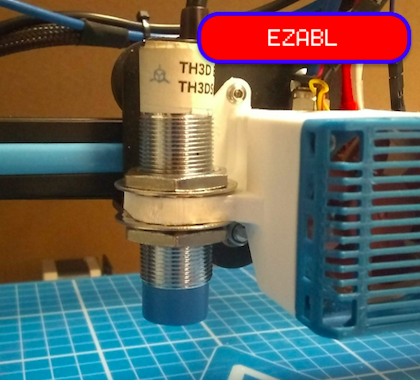
//#define FIX_MOUNTED_PROBE
This option is for any probe that’s fixed in place, with no need to be deployed or stowed. Specify this type for an inductive probe or when using the nozzle itself as the probe.
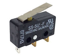
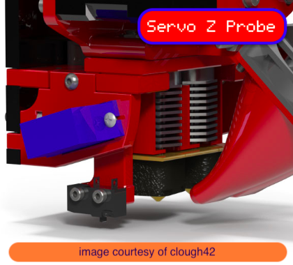
Servo Z Probe
//#define Z_PROBE_SERVO_NR 0       // Defaults to SERVO 0 connector.
//#define Z_SERVO_ANGLES { 70, 0 } // Z Servo Deploy and Stow angles
To indicate a Servo Z Probe (e.g., an endstop switch mounted on a rotating arm) just specify the servo index. Use the M280 command to find the best Z_SERVO_ANGLES values.
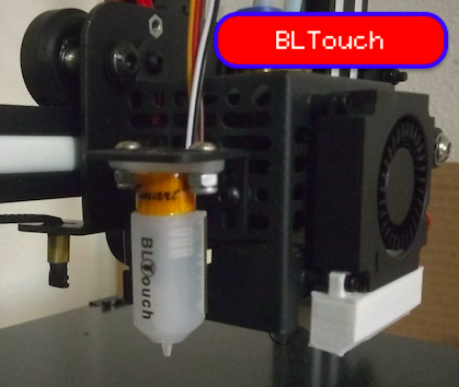
BLTouch
//#define BLTOUCH
The ANTCLABS BLTouch probe uses custom circuitry and a magnet to raise and lower a metal pin which acts as a touch probe. The BLTouch uses the servo connector and is controlled using specific servo angles. With this option enabled the other required settings are automatically configured (so there’s no need to enter servo angles, for example).
TOUCH MI PROBE
//#define TOUCH_MI_PROBE
#if ENABLED(TOUCH_MI_PROBE)
  #define TOUCH_MI_RETRACT_Z 0.5                  // Height at which the probe retracts
  //#define TOUCH_MI_DEPLOY_XPOS (X_MAX_BED + 2)  // For a magnet on the right side of the bed
  //#define TOUCH_MI_MANUAL_DEPLOY                // For manual deploy (LCD menu)
#endif
Touch-MI Probe by hotends.fr is deployed and activated by moving the X-axis to a magnet at the edge of the bed. By default, the magnet is assumed to be on the left and activated by a home. If the magnet is on the right, enable and set TOUCH_MI_DEPLOY_XPOS to the deploy position. Also option requires: BABYSTEPPING, BABYSTEP_ZPROBE_OFFSET, Z_SAFE_HOMING, and a minimum Z_HOMING_HEIGHT of 10.
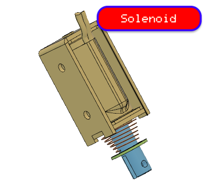
Solenoid Probe
//#define SOLENOID_PROBE
A probe that is deployed and stowed with a solenoid pin (Defined as SOL1_PIN.)
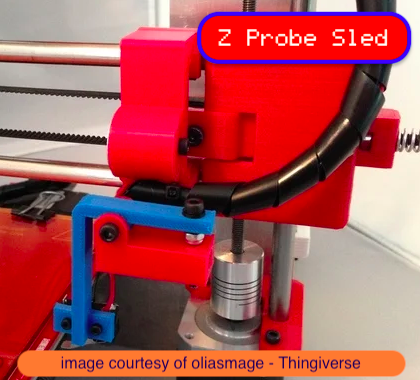
Z Probe Sled
//#define Z_PROBE_SLED
//#define SLED_DOCKING_OFFSET 5
This type of probe is mounted on a detachable “sled” that sits at the far end of the X axis. Before probing, the X carriage moves to the far end and picks up the sled. When probing is completed, it drops the sled off. The SLED_DOCKING_OFFSET specifies the extra distance the X axis must travel to pickup the sled. 0 should be fine but it may be pushed further if needed.
Rack-and-pinion probe
//#define RACK_AND_PINION_PROBE
#if ENABLED(RACK_AND_PINION_PROBE)
  #define Z_PROBE_DEPLOY_X  X_MIN_POS
  #define Z_PROBE_RETRACT_X X_MAX_POS
#endif
A probe deployed by moving the X-axis (e.g., Wilson II’s rack-and-pinion probe designed by Marty Rice.)
Allen Key
//#define Z_PROBE_ALLEN_KEY
A retractable Z-probe for deltas that uses an Allen key as the probe. See “Kossel automatic bed leveling probe” at the RepRap wiki. It deploys by leveraging against the Z-axis belt, and retracts by pushing the probe down.
More information will be included in an upcoming Delta configuration page.
Probe Offsets
These offsets specify the distance from the tip of the nozzle to the probe — or more precisely, to the point at which the probe triggers. The X and Y offsets are specified as integers. The Z offset should be specified as exactly as possible using a decimal value. The Z offset can be overridden with M851 Z or the LCD controller. The M851 offset is saved to EEPROM with M500.
Distance from edge
#define X_PROBE_OFFSET_FROM_EXTRUDER 10  // X offset: -left  +right  [of the nozzle]
#define Y_PROBE_OFFSET_FROM_EXTRUDER 10  // Y offset: -front +behind [the nozzle]
#define Z_PROBE_OFFSET_FROM_EXTRUDER 0   // Z offset: -below +above  [the nozzle]

#define PROBING_MARGIN 10
Certain types of probe need to stay away from the edge
Probing Speed
// X and Y axis travel speed (mm/m) between probes
#define XY_PROBE_FEEDRATE 8000

// Feedrate (mm/m) for the first approach when double-probing (MULTIPLE_PROBING == 2)
#define Z_PROBE_FEEDRATE_FAST HOMING_FEEDRATE_Z

// Feedrate (mm/m) for the "accurate" probe of each point
#define Z_PROBE_FEEDRATE_SLOW (Z_PROBE_FEEDRATE_FAST / 2)
Probing should be done quickly, but the Z speed should be tuned for best repeatability. Depending on the probe, a slower Z probing speed may be needed for repeatable results.
Probe Activation Switch
A switch indicating proper deployment, or an optical switch triggered when the carriage is near the bed.
//#define PROBE_ACTIVATION_SWITCH
#if ENABLED(PROBE_ACTIVATION_SWITCH)
  #define PROBE_ACTIVATION_SWITCH_STATE LOW // State indicating probe is active
  //#define PROBE_ACTIVATION_SWITCH_PIN PC6 // Override default pin
#endif
Probe Tare
Enable this feature to tare the probe (determine zero-point) prior to each probe. Useful for a strain gauge or piezo sensor that needs to factor out elements such as cables pulling on the carriage.
//#define PROBE_TARE
#if ENABLED(PROBE_TARE)
  #define PROBE_TARE_TIME  200    // (ms) Time to hold tare pin
  #define PROBE_TARE_DELAY 200    // (ms) Delay after tare before
  #define PROBE_TARE_STATE HIGH   // State to write pin for tare
  //#define PROBE_TARE_PIN PA5    // Override default pin
  #if ENABLED(PROBE_ACTIVATION_SWITCH)
    //#define PROBE_TARE_ONLY_WHILE_INACTIVE  // Fail to tare/probe if PROBE_ACTIVATION_SWITCH is active
  #endif
#endif
Probe Enable/Disable
Using this feature the probe only provides a triggered signal when enabled. A separate pin is designated to enable the probe.
//#define PROBE_ENABLE_DISABLE
#if ENABLED(PROBE_ENABLE_DISABLE)
  //#define PROBE_ENABLE_PIN -1   // Override the default pin here
#endif
Multiple Probes
//#define MULTIPLE_PROBING 2
//#define EXTRA_PROBING    1
Probing multiple times yields better results. Set to 2 for a fast/slow probe - the second probe result will be used. Set to 3 or more for slow probes - the average result will be used.
Probe Clearance
#define Z_CLEARANCE_DEPLOY_PROBE   10 // Z Clearance for Deploy/Stow
#define Z_CLEARANCE_BETWEEN_PROBES  5 // Z Clearance between probe points
#define Z_CLEARANCE_MULTI_PROBE     5 // Z Clearance between multiple probes
//#define Z_AFTER_PROBING           5 // Z position after probing is done

#define Z_PROBE_LOW_POINT          -2 // Farthest distance below the trigger-point to go before stopping
Z probes require clearance when deploying, stowing, and moving between probe points to avoid hitting the bed and other hardware. Servo-mounted probes require extra space for the arm to rotate. Inductive probes need space to keep from triggering early.
Use these settings to specify the distance (mm) to raise the probe (or lower the bed). The values set here apply over and above any (negative) probe Z Offset set with Z_PROBE_OFFSET_FROM_EXTRUDER, M851, or the LCD. Only integer values >= 1 are valid for these settings.
- Example:
M851 Z-5with a CLEARANCE of 4 => 9 mm from bed to nozzle. - But:
M851 Z+1with a CLEARANCE of 2 => 2 mm from bed to nozzle.
G29 Movement
Make sure you have enough clearance for the probe to move between points!
#define Z_PROBE_OFFSET_RANGE_MIN -20
#define Z_PROBE_OFFSET_RANGE_MAX 20
For M851 and LCD menus give a range for adjusting the Z probe offset.
Probe Testing
#define Z_MIN_PROBE_REPEATABILITY_TEST
This enables you to test the reliability of your probe. Issue a M48 command to start testing. It will give you a standard deviation for the probe. Tip: 0.02mm is normally acceptable for bed leveling to work.
// Before deploy/stow pause for user confirmation
//#define PAUSE_BEFORE_DEPLOY_STOW
#if ENABLED(PAUSE_BEFORE_DEPLOY_STOW)
  //#define PAUSE_PROBE_DEPLOY_WHEN_TRIGGERED // For Manual Deploy Allen Key Probe
#endif
Before deploy/stow pause for user confirmation
Probe with heaters off
//#define PROBING_HEATERS_OFF       // Turn heaters off when probing
#if ENABLED(PROBING_HEATERS_OFF)
  //#define WAIT_FOR_BED_HEATER     // Wait for bed to heat back up between probes (to improve accuracy)
#endif
//#define PROBING_FANS_OFF          // Turn fans off when probing
//#define PROBING_STEPPERS_OFF      // Turn steppers off (unless needed to hold position) when probing
//#define DELAY_BEFORE_PROBING 200  // (ms) To prevent vibrations from triggering piezo sensors
Heating the bed and extruder for probing will produce results that more accurately correspond with your bed if you typically print with the bed heated. Enable PROBING_HEATERS_OFF if you are experiencing electrical noise. A delay can also be added to allow noise and vibration to settle.
Stepper Drivers
Motor Enable
#define X_ENABLE_ON 0
#define Y_ENABLE_ON 0
#define Z_ENABLE_ON 0
//#define I_ENABLE_ON 0
//#define J_ENABLE_ON 0
//#define K_ENABLE_ON 0
//#define U_ENABLE_ON 0
//#define V_ENABLE_ON 0
//#define W_ENABLE_ON 0
#define E_ENABLE_ON 0 // For all extruders
These options set the pin states used for stepper enable. The most common setting is 0 (LOW) for Active Low. For Active High use 1 or HIGH.
Motor Disable
#define DISABLE_X false
#define DISABLE_Y false
#define DISABLE_Z false
//#define DISABLE_I false
//#define DISABLE_J false
//#define DISABLE_K false
//#define DISABLE_U false
//#define DISABLE_V false
//#define DISABLE_W false
Use these options to disable steppers when not being issued a movement. This was implemented as a hack to run steppers at higher-than-normal current in an effort to produce more torque at the cost of increased heat for drivers and steppers.
Disabling the steppers between moves gives the motors and drivers a chance to cool off. It sounds good in theory, but in practice it has drawbacks. Disabled steppers can’t hold the carriage stable. This results in poor accuracy and carries a strong probability of axial drift (i.e., lost steps).
Most 3D printers use an “open loop” control system, meaning the software can’t ascertain the actual carriage position at a given time. It simply sends commands and assumes they have been obeyed. In practice with a well-calibrated machine this is not an issue and using open loop is a major cost saving with excellent quality.
We don’t recommend this hack. There are much better ways to address the problem of stepper/driver overheating. Some examples: stepper/driver heatsink, active cooling, dual motors on the axis, reduce micro-stepping, check belt for over tension, check components for smooth motion, etc.
//#define DISABLE_REDUCED_ACCURACY_WARNING
Enable this option to suppress the warning given in cases when reduced accuracy is likely to occur.
#define DISABLE_E false 					// For all extruders
#define DISABLE_INACTIVE_EXTRUDER	false 	// Keep only the active extruder enabled
The E disable option works like DISABLE_[XYZ] but pertains to one or more extruders. The default setting keeps the active extruder enabled, disabling all inactive extruders. This is reasonable for situations where a “wipe tower” or other means is used to ensure that the nozzle is primed and not oozing between uses.
Motor Direction
#define INVERT_X_DIR false
#define INVERT_Y_DIR true
#define INVERT_Z_DIR false
//#define INVERT_I_DIR false
//#define INVERT_J_DIR false
//#define INVERT_K_DIR false
//#define INVERT_U_DIR false
//#define INVERT_V_DIR false
//#define INVERT_W_DIR false

#define INVERT_E0_DIR false
#define INVERT_E1_DIR false
#define INVERT_E2_DIR false
#define INVERT_E3_DIR false
#define INVERT_E4_DIR false
These settings reverse the motor direction for each axis. Be careful when first setting these. Axes moving the wrong direction can cause damage. Get these right without belts attached first, if possible. Before testing, move the carriage and bed to the middle. Test each axis for proper movement using the host or LCD “Move Axis” menu. If an axis is inverted, either flip the plug around or change its invert setting.
Homing and Bounds
Z Homing Height

//#define NO_MOTION_BEFORE_HOMING	// Inhibit movement until all axes have been homed
//#define UNKNOWN_Z_NO_RAISE		// Don't raise Z (lower the bed) if Z is "unknown."
									//For beds that fall when Z is powered off.
//#define Z_HOMING_HEIGHT 4
This value raises Z to the specified height above the bed before homing X or Y. This is useful to prevent the head crashing into bed mountings such as screws, bulldog clips, etc. This also works with auto bed leveling enabled and will be triggered only when the Z axis height is less than the defined value, otherwise the Z axis will not move. NO_MOTION_BEFORE_HOMING and UNKNOWN_Z_NO_RAISE
Homing Direction
#define X_HOME_DIR -1
#define Y_HOME_DIR -1
#define Z_HOME_DIR -1
//#define I_HOME_DIR -1
//#define J_HOME_DIR -1
//#define K_HOME_DIR -1
//#define U_HOME_DIR -1
//#define V_HOME_DIR -1
//#define W_HOME_DIR -1
Homing direction for each axis: -1 = min, 1 = max. Most Cartesian and core machines have three min endstops. Deltas have three max endstops. For other configurations set these values appropriately.
Movement Bounds
#define X_BED_SIZE 200
#define Y_BED_SIZE 200
With Marlin you can directly specify the bed size. This allows Marlin to do extra logic related to the bed size when it differs from the movement limits below. If the XY carriage is able to move outside of the bed, you can specify a wider range below.
#define X_MIN_POS 0
#define Y_MIN_POS 0
#define Z_MIN_POS 0
#define X_MAX_POS X_BED_SIZE
#define Y_MAX_POS Y_BED_SIZE
#define Z_MAX_POS 200
//#define I_MIN_POS 0
//#define I_MAX_POS 50
//#define J_MIN_POS 0
//#define J_MAX_POS 50
//#define K_MIN_POS 0
//#define K_MAX_POS 50
//#define U_MIN_POS 0
//#define U_MAX_POS 50
//#define V_MIN_POS 0
//#define V_MAX_POS 50
//#define W_MIN_POS 0
//#define W_MAX_POS 50
These values specify the physical limits of the machine. Usually the [XYZ]_MIN_POS values are set to 0, because endstops are positioned at the bed limits. [XYZ]_MAX_POS should be set to the farthest reachable point. By default, these are used as your homing positions as well. However, the MANUAL_[XYZ]_HOME_POS options can be used to override these, if needed.
Home Offset
Although home positions are fixed, M206 can be used to apply offsets to the home position if needed.
Software Endstops
#define MIN_SOFTWARE_ENDSTOPS
#if ENABLED(MIN_SOFTWARE_ENDSTOPS)
  #define MIN_SOFTWARE_ENDSTOP_X
  #define MIN_SOFTWARE_ENDSTOP_Y
  #define MIN_SOFTWARE_ENDSTOP_Z
  #define MIN_SOFTWARE_ENDSTOP_I
  #define MIN_SOFTWARE_ENDSTOP_J
  #define MIN_SOFTWARE_ENDSTOP_K
  #define MIN_SOFTWARE_ENDSTOP_U
  #define MIN_SOFTWARE_ENDSTOP_V
  #define MIN_SOFTWARE_ENDSTOP_W
#endif

#define MAX_SOFTWARE_ENDSTOPS
#if ENABLED(MAX_SOFTWARE_ENDSTOPS)
  #define MAX_SOFTWARE_ENDSTOP_X
  #define MAX_SOFTWARE_ENDSTOP_Y
  #define MAX_SOFTWARE_ENDSTOP_Z
  #define MAX_SOFTWARE_ENDSTOP_I
  #define MAX_SOFTWARE_ENDSTOP_J
  #define MAX_SOFTWARE_ENDSTOP_K
  #define MAX_SOFTWARE_ENDSTOP_U
  #define MAX_SOFTWARE_ENDSTOP_V
  #define MAX_SOFTWARE_ENDSTOP_W
#endif
Enable these options to constrain movement to the physical boundaries of the machine (as set by [XYZIJKUVW]_(MIN|MAX)_POS). For example, G1 Z-100 can be min constrained to G1 Z0. It is recommended to enable these options as a safety feature. If software endstops need to be disabled, use M211 S0.
#if EITHER(MIN_SOFTWARE_ENDSTOPS, MAX_SOFTWARE_ENDSTOPS)
  //#define SOFT_ENDSTOPS_MENU_ITEM
#endif
Enable/Disable software endstops from the LCD
Filament Runout Sensor
//#define FILAMENT_RUNOUT_SENSOR
#if ENABLED(FILAMENT_RUNOUT_SENSOR)
  #define NUM_RUNOUT_SENSORS   1     // Number of sensors, up to one per extruder. Define a FIL_RUNOUT#_PIN for each.
  #define FIL_RUNOUT_INVERTING false // Set to true to invert the logic of the sensor.
  #define FIL_RUNOUT_PULLUP          // Use internal pullup for filament runout pins.
  //#define FIL_RUNOUT_PULLDOWN      // Use internal pulldown for filament runout pins.

  // Set one or more commands to execute on filament runout.
  // (After 'M412 H' Marlin will ask the host to handle the process.)
  #define FILAMENT_RUNOUT_SCRIPT "M600"

  // When using a runout switch (no encoder), after a runout is detected,
  // continue printing this length of filament before executing the runout script.
  // Useful for a sensor at the end of a feed tube.
  // If using an encoder disc, this is the length of filament that would print
  // without any movement from the sensor before it triggers a runout.
  // Requires 4 bytes SRAM per sensor, plus 4 bytes overhead.
  //#define FILAMENT_RUNOUT_DISTANCE_MM 25

  #ifdef FILAMENT_RUNOUT_DISTANCE_MM
    // Enable this option to use an encoder disc that toggles the runout pin as the filament moves.
    // Be sure to set FILAMENT_RUNOUT_DISTANCE_MM large enough to avoid false positives.
    // Start at the value of the sensor for one revolution and if you experience false positives,
    // increment the value by the same amount.
    // e.g., If set to 7mm and you get false positives, set it to 14 and try again.
    //#define FILAMENT_MOTION_SENSOR
  #endif
#endif
With this feature, a mechanical or opto endstop switch is used to check for the presence of filament in the feeder (usually the switch is closed when filament is present). If the filament runs out, Marlin will run the specified G-code script (by default M600).
RAMPS-based boards use SERVO3_PIN. For other boards you may need to define FIL_RUNOUT_PIN. Enable the M43 feature in your firmware (PINS_DEBUGGING) and load it to your printer. Assuming you already have a runout sensor (switch based) there, you can watch the pin states while toggling the runout sensor on an off to see which pin is changing.
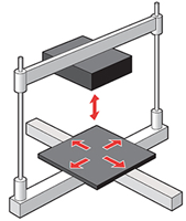
Bed Leveling
Bed Leveling is a standard feature on many 3D printers. It takes the guess-work out of getting a good first layer and good bed adhesion.
It is highly recommended to get your printer aligned and constrained as much as possible before using bed leveling, because it exists to compensate for imperfections in the hardware.
For all the in-depth details please read the Auto Bed Leveling documentation and the G29 G-codes documentation.
With Bed Leveling enabled:
- | By default
G28disables bed leveling. FollowG28withM420 Sto turn leveling on.- With
ENABLE_LEVELING_AFTER_G28leveling will always be enabled afterG28. - With
RESTORE_LEVELING_AFTER_G28leveling is restored to whatever state it was in beforeG28.
- With
-
G29will automatically probe the bed or guide you to do a paper-test at various points. After measurement it calculates a correction grid or matrix and enables leveling compensation. The specific behavior depends on configuration and type of bed leveling. -
M500will save the bed leveling data to EEPROM.M501will load it.M502will erase it. AndM503will report it. -
M420 S<bool>can be used to enable/disable bed leveling. For example,M420 S1must be used afterM501to enable the loaded mesh or matrix, and to re-enable leveling afterG28, which disables leveling compensation. - A “Level Bed” menu item can be added to the LCD with the
LCD_BED_LEVELINGoption.
//#define AUTO_BED_LEVELING_3POINT
//#define AUTO_BED_LEVELING_LINEAR
//#define AUTO_BED_LEVELING_BILINEAR
//#define AUTO_BED_LEVELING_UBL
//#define MESH_BED_LEVELING
Enable just one type of Bed Leveling.
-
AUTO_BED_LEVELING_3POINTprobes three points in a triangle. The flat plane gives a transform matrix suitable to compensate for a flat but tilted bed. -
AUTO_BED_LEVELING_LINEARprobes the bed in a grid. A transform matrix is produced by least-squares method to compensate for a flat but tilted bed. -
AUTO_BED_LEVELING_BILINEARprobes the bed in a grid, with optional Catmull-Rom subdivision. The mesh data is used to adjust Z height across the bed using bilinear interpolation. Good for delta, large, or uneven beds. -
AUTO_BED_LEVELING_UBL(recommended) combines the features of 3-point, linear, bilinear, and mesh leveling. As with bilinear leveling, the mesh data generated by UBL is used to adjust Z height across the bed using bilinear interpolation. An LCD controller is currently required. -
MESH_BED_LEVELINGprovides a customG29command to measure the bed height at several grid points using a piece of paper or feeler gauge. SeeG29for MBL for the full procedure. This type of leveling is only compatible withPROBE_MANUALLY.
Only AUTO_BED_LEVELING_BILINEAR and AUTO_BED_LEVELING_UBL support DELTA.
Only AUTO_BED_LEVELING_BILINEAR currently supports SCARA.
MESH_BED_LEVELING is incompatible with Delta and SCARA.
Restore after G28
//#define RESTORE_LEVELING_AFTER_G28
Normally G28 causes leveling to be disabled, so you have to re-enable it with M420 S1 or G29. If you enable this option then G28 will make sure to turn leveling back on if it was enabled beforehand.
Debug Leveling
//#define DEBUG_LEVELING_FEATURE
Use this option to enable extra debugging of homing and leveling. You can then use M111 S32 before issuing G28 and G29 V4 to get a detailed log of the process for diagnosis. This option is useful to figure out the cause of unexpected behaviors, or when reporting issues to the project.
Leveling Fade Height
#define ENABLE_LEVELING_FADE_HEIGHT
Available with MESH_BED_LEVELING, AUTO_BED_LEVELING_BILINEAR, and AUTO_BED_LEVELING_UBL.
This option adds the Z parameter to M420 which sets a fade distance over which leveling will be gradually reduced. Above the given Z height, leveling compensation will no longer be applied.
This feature exists to prevent irregularities in the bed from propagating through the model’s entire height. Fading out leveling also reduces computational requirements and resonance from the Z axis above the fade height. For a well-aligned machine, this feature can improve print results.
Example: To have leveling fade out over the first 10mm of layer printing use M420 Z10. If each layer is 0.2 mm high, leveling compensation will be reduced by 1/50th (2 %) after each layer. Above 10mm the machine will move without compensation.
G26 Mesh Validation Pattern
/**
 * Enable the G26 Mesh Validation Pattern tool.
 */
#define G26_MESH_VALIDATION   // Enable G26 mesh validation
#if ENABLED(G26_MESH_VALIDATION)
  #define MESH_TEST_NOZZLE_SIZE     0.4   // (mm) Diameter of primary nozzle.
  #define MESH_TEST_LAYER_HEIGHT    0.2   // (mm) Default layer height for the G26 Mesh Validation Tool.
  #define MESH_TEST_HOTEND_TEMP   205   // (°C) Default nozzle temperature for the G26 Mesh Validation Tool.
  #define MESH_TEST_BED_TEMP       60   // (°C) Default bed temperature for the G26 Mesh Validation Tool.
  #define G26_XY_FEEDRATE         20    // (mm/s) Feedrate for XY Moves for the G26 Mesh Validation Tool.

#endif
When using any of the mesh-based leveling systems (1.1.7) you can activate G26_MESH_VALIDATION to print test patterns and fine-tune the mesh. See G26 Mesh Validation for full details. The G26 command accepts parameters for nozzle size, layer height, etc. The sub-options above specify the default values that will be applied for omitted parameters.
Linear / Bilinear Options
#define GRID_MAX_POINTS_X 3
#define GRID_MAX_POINTS_Y GRID_MAX_POINTS_X
These options specify the default number of points to probe in each dimension during G29.
//#define PROBING_MARGIN_LEFT PROBING_MARGIN
//#define PROBING_MARGIN_RIGHT PROBING_MARGIN
//#define PROBING_MARGIN_FRONT PROBING_MARGIN
//#define PROBING_MARGIN_BACK PROBING_MARGIN
These settings specify the boundaries for probing with G29. This will most likely be a sub-section of the bed because probes are not usually able to reach every point that the nozzle can. Take account of the probe’s XY offsets when setting these boundaries.
//#define PROBE_Y_FIRST
Enable this option if probing should proceed in the Y dimension first instead of X first.
Bilinear Options
//#define EXTRAPOLATE_BEYOND_GRID
Usually the probed grid doesn’t extend all the way to the edges of the bed. So, outside the bounds of the probed grid, Z adjustment can take one of two approaches. Either the Z height can continue to raise/lower by the established tilt of the nearest grid box (best when most of the bed was probed), or it can follow the contour of the nearest edge (the default). Enable this option for extrapolation.
//#define ABL_BILINEAR_SUBDIVISION
#if ENABLED(ABL_BILINEAR_SUBDIVISION)
  // Number of subdivisions between probe points
  #define BILINEAR_SUBDIVISIONS 3
#endif
If you have SRAM to spare, this option will multiply the resolution of the bilinear grid using the Catmull-Rom subdivision method. This option only applies to bilinear leveling. If the default value of 3 is too expensive, try 2 or 1. (In Marlin 1.1.1, the default grid will be stored in PROGMEM, as UBL now does.)
Unified Bed Leveling Options
Probe Points
#define UBL_MESH_INSET 1          // Mesh inset margin on print area
#define GRID_MAX_POINTS_X 10      // Don't use more than 15 points per axis, implementation limited.
#define GRID_MAX_POINTS_Y GRID_MAX_POINTS_X

  #define UBL_MESH_EDIT_MOVES_Z     // Sophisticated users prefer no movement of nozzle
  #define UBL_SAVE_ACTIVE_ON_M500   // Save the currently active mesh in the current slot on M500

  //#define UBL_Z_RAISE_WHEN_OFF_MESH 2.5 // When the nozzle is off the mesh, this value is used
                                          // as the Z-Height correction value.
These options specify the inset, grid, and 3-point triangle to use for UBL. Note that probe XY offsets and movement limits may constrain the probeable area of the bed.
Mesh Bed Leveling Options
#define MESH_INSET 10          // Mesh inset margin on print area
#define GRID_MAX_POINTS_X 3    // Don't use more than 7 points per axis, implementation limited.
#define GRID_MAX_POINTS_Y GRID_MAX_POINTS_X

//#define MESH_G28_REST_ORIGIN // After homing all axes ('G28' or 'G28 XYZ') rest Z at Z_MIN_POS
These options specify the number of points that will always be probed in each dimension during G29. The mesh inset is used to automatically calculate the probe boundaries. These can be set explicitly in Configuration_adv.h. MESH_G28_REST_ORIGIN moves the nozzle to rest at Z_MIN_POS when mesh probing is done. If Z is offset (e.g., due to home_offset or some other cause) this is intended to move Z to a good starting point, usually Z=0.
LCD Bed Leveling
//#define LCD_BED_LEVELING
#if ENABLED(LCD_BED_LEVELING)
  #define MESH_EDIT_Z_STEP  0.025 // (mm) Step size while manually probing Z axis.
  #define LCD_PROBE_Z_RANGE 4     // (mm) Z Range centered on Z_MIN_POS for LCD Z adjustment
  //#define MESH_EDIT_MENU        // Add a menu to edit mesh points
#endif
LCD_BED_LEVELING adds a “Level Bed” menu to the LCD that starts a step-by-step guided leveling procedure that requires no probe.
Available with MESH_BED_LEVELING and PROBE_MANUALLY (all forms of Auto Bed Leveling). See the Configuration.h file for sub-options and the G29 G-code documentation that applies to your selected leveling system.
Corner Leveling
//#define LEVEL_BED_CORNERS
#if ENABLED(LEVEL_BED_CORNERS)
  #define LEVEL_CORNERS_INSET 30    // (mm) An inset for corner leveling
  #define LEVEL_CORNERS_Z_HOP  4.0  // (mm) Move nozzle up before moving between corners
  #define LEVEL_CORNERS_HEIGHT 0.0  // (mm) Z height of nozzle at leveling points
  //#define LEVEL_CENTER_TOO        // Move to the center after the last corner
#endif
Add a menu item to move between bed corners for manual bed adjustment.
Z Probe End Script
//#define Z_PROBE_END_SCRIPT "G1 Z10 F12000\nG1 X15 Y330\nG1 Z0.5\nG1 Z10"
A custom script to do at the very end of G29. If multiple commands are needed, divide them with \n (the newline character).
Homing Options
Bed Center at 0,0
//#define BED_CENTER_AT_0_0
Enable this option if the bed center is at X0 Y0. This setting affects the way automatic home positions (those not set with MANUAL_[XYZ]_POS) are calculated. This should always be enabled with DELTA.
Manual Home Position
//#define MANUAL_X_HOME_POS 0
//#define MANUAL_Y_HOME_POS 0
//#define MANUAL_Z_HOME_POS 0 // Distance from nozzle to print bed after homing
//#define MANUAL_I_HOME_POS 0
//#define MANUAL_J_HOME_POS 0
//#define MANUAL_K_HOME_POS 0
//#define MANUAL_U_HOME_POS 0
//#define MANUAL_V_HOME_POS 0
//#define MANUAL_W_HOME_POS 0
These settings are used to override the home position. Leave them undefined for automatic settings. For DELTA Z home must be set to the top-most position.
Z Safe Homing
#define Z_SAFE_HOMING

#if ENABLED(Z_SAFE_HOMING)
  #define Z_SAFE_HOMING_X_POINT ((X_BED_SIZE) / 2)    // X point for Z homing when homing all axes (G28).
  #define Z_SAFE_HOMING_Y_POINT ((Y_BED_SIZE) / 2)    // Y point for Z homing when homing all axes (G28).
#endif
Z Safe Homing prevents Z from homing when the probe (or nozzle) is outside bed area by moving to a defined XY point (by default, the middle of the bed) before Z Homing when homing all axes with G28. As a side-effect, X and Y homing are required before Z homing. If stepper drivers time out, X and Y homing will be required again.
Enable this option if a probe (not an endstop) is being used for Z homing. Z Safe Homing isn’t needed if a Z endstop is used for homing, but it may also be enabled just to have XY always move to some custom position after homing.
Homing Speed
// Homing speeds (mm/m)
#define HOMING_FEEDRATE_XY (50*60)
#define HOMING_FEEDRATE_Z  (4*60)
Homing speed for use in auto home and auto bed leveling. These values may be set to the fastest speeds your machine can achieve. Homing and probing speeds are constrained by the current max feedrate and max acceleration settings.
Setting these values too high may result in reduced accuracy and/or skipped steps. Reducing acceleration may help to achieve higher top speeds.
#define VALIDATE_HOMING_ENDSTOPS
Validate that endstops are triggered on homing moves.
Bed Skew Compensation
//#define SKEW_CORRECTION

#if ENABLED(SKEW_CORRECTION)
  // Input all length measurements here:
  #define XY_DIAG_AC 282.8427124746
  #define XY_DIAG_BD 282.8427124746
  #define XY_SIDE_AD 200

  // Or, set the default skew factors directly here
  // to override the above measurements:
  #define XY_SKEW_FACTOR 0.0

  //#define SKEW_CORRECTION_FOR_Z
  #if ENABLED(SKEW_CORRECTION_FOR_Z)
    #define XZ_DIAG_AC 282.8427124746
    #define XZ_DIAG_BD 282.8427124746
    #define YZ_DIAG_AC 282.8427124746
    #define YZ_DIAG_BD 282.8427124746
    #define YZ_SIDE_AD 200
    #define XZ_SKEW_FACTOR 0.0
    #define YZ_SKEW_FACTOR 0.0
  #endif

  // Enable this option for M852 to set skew at runtime
  //#define SKEW_CORRECTION_GCODE
#endif
Correct for misalignment in the XYZ axes. See Configuration.h for a thorough explanation.
Additional Features
EEPROM
//#define EEPROM_SETTINGS
Commands like M92 only change the settings in volatile memory, and these settings are lost when the machine is powered off. With this option enabled, Marlin uses the built-in EEPROM to preserve settings across reboots. Settings saved to EEPROM (with M500) are loaded automatically whenever the machine restarts (and in most setups, when connecting to a host), overriding the defaults set in the configuration files. This option is highly recommended, as it makes configurations easier to manage.
The EEPROM-related commands are:
-
M500: Save all current settings to EEPROM. -
M501: Load all settings last saved to EEPROM. -
M502: Reset all settings to their default values (as set byConfiguration.h) -
M503: Print the current settings (in RAM, not EEPROM)
EEPROM Options
//#define DISABLE_M503    // Saves ~2700 bytes of PROGMEM. Disable for release!
#define EEPROM_CHITCHAT   // Give feedback on EEPROM commands. Disable to save PROGMEM.
These EEPROM options should be left as they are, but for 128K and smaller boards they may be used to recover some program memory. Vendors are strongly discouraged from using DISABLE_M503.
Settings that can be changed and saved to EEPROM are marked with . Options marked with can be changed from the LCD controller.
Host Keepalive
#define HOST_KEEPALIVE_FEATURE        // Disable this if your host doesn't like keepalive messages
#define DEFAULT_KEEPALIVE_INTERVAL 2  // Number of seconds between "busy" messages. Set with M113.
#define BUSY_WHILE_HEATING            // Some hosts require "busy" messages even during heating
When Host Keepalive is enabled Marlin will send a busy status message to the host every couple of seconds when it can’t accept commands. Disable if your host doesn’t like keepalive messages. Use DEFAULT_KEEPALIVE_INTERVAL for the default number of seconds between “busy” messages. Override with M113. Marlin 1.1.5 and up include the BUSY_WHILE_HEATING option for hosts that treat host keepalive as a strict busy protocol.
Free Memory Watcher
//#define M100_FREE_MEMORY_WATCHER
Uncomment to add the M100 Free Memory Watcher for debugging purposes.
Inch Units
//#define INCH_MODE_SUPPORT
This option adds support for the G20 and G21 commands, allowing G-code to specify units in inches.
Temperature Units
//#define TEMPERATURE_UNITS_SUPPORT
This option adds support for M149 C, M149 K, and M149 F to set temperature units to Celsius, Kelvin, or Fahrenheit. Without this option all temperatures must be specified in Celsius units.
LCD Material Presets
#define PREHEAT_1_TEMP_HOTEND 180
#define PREHEAT_1_TEMP_BED     70
#define PREHEAT_1_FAN_SPEED     0 // Value from 0 to 255

#define PREHEAT_2_TEMP_HOTEND 240
#define PREHEAT_2_TEMP_BED    110
#define PREHEAT_2_FAN_SPEED     0 // Value from 0 to 255
These are the default values for the Prepare > Preheat LCD menu options. These values can be overridden using the M145 command or the Control > Temperature > Preheat Material X conf submenus.
Nozzle Park
//#define NOZZLE_PARK_FEATURE
#if ENABLED(NOZZLE_PARK_FEATURE)
  // Specify a park position as { X, Y, Z_raise }
  #define NOZZLE_PARK_POINT { (X_MIN_POS + 10), (Y_MAX_POS - 10), 20 }
  #define NOZZLE_PARK_XY_FEEDRATE 100   // (mm/s) X and Y axes feedrate (also used for delta Z axis)
  #define NOZZLE_PARK_Z_FEEDRATE 5      // (mm/s) Z axis feedrate (not used for delta printers)
#endif
Park the nozzle at the given XYZ position on idle or G27.
The “P” parameter controls the action applied to the Z axis:
-
P0- (Default) If Z is below park Z raise the nozzle. -
P1- Raise the nozzle always to Z-park height. -
P2- Raise the nozzle by Z-park amount, limited toZ_MAX_POS.
Nozzle Clean
//#define NOZZLE_CLEAN_FEATURE
#if ENABLED(NOZZLE_CLEAN_FEATURE)
  // Default number of pattern repetitions
  #define NOZZLE_CLEAN_STROKES  12

  // Default number of triangles
  #define NOZZLE_CLEAN_TRIANGLES  3

  // Specify positions as { X, Y, Z }
  #define NOZZLE_CLEAN_START_POINT { 30, 30, (Z_MIN_POS + 1)}
  #define NOZZLE_CLEAN_END_POINT   { 100, 60, (Z_MIN_POS + 1) }

  // Circular pattern radius
  #define NOZZLE_CLEAN_CIRCLE_RADIUS 6.5
  // Circular pattern circle fragments number
  #define NOZZLE_CLEAN_CIRCLE_FN 10
  // Middle point of circle
  #define NOZZLE_CLEAN_CIRCLE_MIDDLE NOZZLE_CLEAN_START_POINT

  // Move the nozzle to the initial position after cleaning
  #define NOZZLE_CLEAN_GOBACK

  // Enable for a purge/clean station that's always at the gantry height (thus no Z move)
  //#define NOZZLE_CLEAN_NO_Z
#endif
Adds the G12 command to perform a nozzle cleaning process. See Configuration.h for additional configuration options.
Print Job Timer
#define PRINTJOB_TIMER_AUTOSTART
Automatically start and stop the print job timer when M104/M109/M190 commands are received. Also adds the following commands to control the timer:
Print Counter
//#define PRINTCOUNTER
When enabled Marlin will keep track of some print statistics such as:
- Total print jobs
- Total successful print jobs
- Total failed print jobs
- Total time printing
This information can be viewed by the M78 command.
User Interface Language
#define LCD_LANGUAGE en
Choose your preferred language for the LCD controller here. Supported languages include:
| Code | Language | Code | Language | Code | Language | ||
|---|---|---|---|---|---|---|---|
| en | English (Default) | an | Aragonese | bg | Bulgarian | ||
| ca | Catalan | cz | Czech | da | Danish | ||
| de | German | el | Greek | el_CY | Greek (Cyprus) | ||
| el_gr | Greek (Greece) | es | Spanish | eu | Basque-Euskera | ||
| fi | Finnish | fr | French | fr_na | French (no accent) | ||
| gl | Galician | hr | Croatian (Hrvatski) | hu | Hungarian / Magyar | ||
| it | Italian | jp_kana | Japanese (Kana) | ko_KR | Korean | ||
| nl | Dutch | pl | Polish | pt | Portuguese | ||
| pt_br | Portuguese (Brazil) | ro | Romanian | ru | Russian | ||
| sk | Slovak | sv | Swedish | tr | Turkish | ||
| uk | Ukrainian | vi | Vietnamese | zh_CN | Simplified Chinese | ||
| zh_TW | Traditional Chinese |
See language.h for the latest list of supported languages and their international language codes.
HD44780 Character Set
#define DISPLAY_CHARSET_HD44780 JAPANESE
This option applies only to character-based displays. Character-based displays (based on the Hitachi HD44780) provide an ASCII character set plus one of the following language extensions:
-
JAPANESE… the most common -
WESTERN…. with more accented characters -
CYRILLIC… for the Russian language
To determine the language extension installed on your controller:
- Compile and upload with
LCD_LANGUAGEset to ‘test’ - Click the controller to view the LCD menu
- The LCD will display Japanese, Western, or Cyrillic text
See LCD Language System for in-depth info on how the Marlin display system currently works.
LCD_INFO_SCREEN_STYLE
#define LCD_INFO_SCREEN_STYLE 0
0 for classic; 1 for Průša info screen style.
SD Card
//#define SDSUPPORT
Enable to use SD printing, whether as part of an LCD controller or as a standalone SDCard slot.
The SDSUPPORT option must be enabled or SD printing will not be supported. It is no longer enabled automatically for LCD controllers with built-in SDCard slot.
SD SPI Speed
//#define SD_SPI_SPEED SPI_HALF_SPEED
Uncomment to enable and set ONE of these options to use a slower SPI transfer speed, otherwise full speed will be applied:
SPI_HALF_SPEEDSPI_QUARTER_SPEED-
SPI_EIGHTH_SPEEDThis is usually required if you’re getting volume init errors.
Enable CRC
//#define SD_CHECK_AND_RETRY
Use CRC checks and retries on the SD communication.
LCD Menu Items
//#define NO_LCD_MENUS
//#define SLIM_LCD_MENUS
Disable all menus and only display the Status Screen with NO_LCD_MENUS, or just remove some extraneous menu items to recover space with SLIM_LCD_MENUS.
Encoder
Encoder Resolution
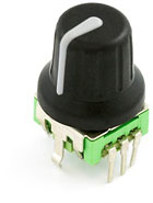
//#define ENCODER_PULSES_PER_STEP 1
This option overrides the default number of encoder pulses needed to produce one step. Should be increased for high-resolution encoders.
//#define ENCODER_STEPS_PER_MENU_ITEM 5
Use this option to override the number of step signals required to move between next/prev menu items.
Encoder Direction
Test your encoder’s behavior first with both of the following options disabled.
- Reversed Value Edit and Menu Nav? Enable
REVERSE_ENCODER_DIRECTION. - Reversed Menu Navigation only? Enable
REVERSE_MENU_DIRECTION. - Reversed Value Editing only? Enable BOTH options.
//#define REVERSE_ENCODER_DIRECTION
This option reverses the encoder direction everywhere. Set if CLOCKWISE causes values to DECREASE.
//#define REVERSE_MENU_DIRECTION
This option reverses the encoder direction for navigating LCD menus. If CLOCKWISE normally moves DOWN this makes it go UP. If CLOCKWISE normally moves UP this makes it go DOWN.
//#define REVERSE_SELECT_DIRECTION
This option reverses the encoder direction for Select Screen If CLOCKWISE normally moves LEFT this makes it go RIGHT. If CLOCKWISE normally moves RIGHT this makes it go LEFT.
//#define INDIVIDUAL_AXIS_HOMING_MENU
Add individual axis homing items (Home X, Home Y, and Home Z) to the LCD menu.
Speaker
//#define SPEAKER
By default Marlin assumes you have a buzzer with a fixed frequency. If you have a speaker that can produce tones, enable it here.
//#define LCD_FEEDBACK_FREQUENCY_DURATION_MS 100
//#define LCD_FEEDBACK_FREQUENCY_HZ 1000
The duration and frequency for the UI feedback sound. Set these to 0 to disable audio feedback in the LCD menus. Test audio output with the G-code M300 S<frequency Hz> P<duration ms>
LCD Controller
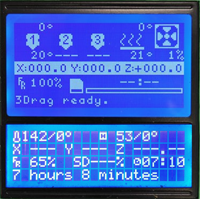
Marlin includes support for several controllers. The two most popular controllers supported by Marlin are:
-
REPRAP_DISCOUNT_SMART_CONTROLLERA 20 x 4 character-based LCD controller with click-wheel. -
REPRAP_DISCOUNT_FULL_GRAPHIC_SMART_CONTROLLERA monochrome 128 x 64 pixel-based LCD controller with click-wheel. Able to display simple bitmap graphics and up to 5 lines of text.
Most other LCD controllers are variants of these. Enable just one of the following options for your specific controller:
Character LCDs
| Option | Description |
|---|---|
ULTIMAKERCONTROLLER | The original Ultimaker Controller. |
ULTIPANEL | ULTIPANEL as seen on Thingiverse. |
PANEL_ONE | PanelOne from T3P3 (via RAMPS 1.4 AUX2/AUX3). A variant of ULTIMAKERCONTROLLER. |
REPRAP_DISCOUNT_SMART_CONTROLLER | RepRapDiscount Smart Controller. Usually sold with a white PCB. |
G3D_PANEL | Gadgets3D G3D LCD/SD Controller. Usually sold with a blue PCB. |
RIGIDBOT_PANEL | RigidBot Panel V1.0. |
ANET_KEYPAD_LCD | Anet Keypad LCD for the Anet A3 |
Graphical LCDs
| Option | Description |
|---|---|
CARTESIO_UI | Cartesio UI. |
MAKRPANEL | MaKr3d Makr-Panel with graphic controller and SD support. |
REPRAPWORLD_GRAPHICAL_LCD | ReprapWorld Graphical LCD. |
VIKI2 | Panucatt Devices Viki 2.0. |
miniVIKI | mini Viki with Graphic LCD. |
ELB_FULL_GRAPHIC_CONTROLLER | Adafruit ST7565 Full Graphic Controller. |
REPRAP_DISCOUNT_FULL_GRAPHIC_SMART_CONTROLLER | RepRapDiscount Full Graphic Smart Controller. |
MINIPANEL | MakerLab Mini Panel with graphic controller and SD support. |
BQ_LCD_SMART_CONTROLLER | BQ LCD Smart Controller shipped with the BQ Hephestos 2 and Witbox 2. |
ANET_FULL_GRAPHICS_LCD | Anet Full Graphics LCD for the Anet A3 |
Keypads
| Option | Description |
|---|---|
REPRAPWORLD_KEYPAD | RepRapWorld Keypad v1.1 Use REPRAPWORLD_KEYPAD_MOVE_STEP to set how much the robot should move on each keypress (e.g., 10mm per click). |
I2C Character LCDs
These controllers all require the LiquidCrystal_I2C library.
| Option | Description |
|---|---|
RA_CONTROL_PANEL | Elefu RA Board Control Panel |
LCD_I2C_SAINSMART_YWROBOT | Sainsmart YWRobot LCM1602 LCD Display. |
LCM1602 | Generic LCM1602 LCD adapter |
LCD_I2C_PANELOLU2 | PANELOLU2 LCD with status LEDs, separate encoder and click inputs. The click input can either be directly connected to a pin (if BTN_ENC is defined) or read through I2C (with BTN_ENC undefined). Requires LiquidTWI2 library v1.2.3 or later. |
LCD_I2C_VIKI | Panucatt VIKI LCD with status LEDs, integrated click & L/R/U/D buttons, separate encoder inputs. |
SAV_3DLCD | Shift register panels. 2 wire Non-latching LCD SR. See LCD configuration. |
I2C Graphical LCDs
These controllers all require the LiquidCrystal_I2C library.
| Option | Description |
|---|---|
U8GLIB_SSD1306 | SSD1306 OLED full graphics generic display. |
SAV_3DGLCD | SAV OLED LCD module support using either SSD1306 or SH1106 based LCD modules. |
OLED_PANEL_TINYBOY2 | TinyBoy2 128x64 OLED / Encoder Panel |
Fan PWM
//#define FAST_PWM_FAN
Increase the FAN PWM frequency. Removes the PWM noise but increases heating in the FET/Arduino.
//#define FAN_SOFT_PWM
Use software PWM to drive the fan, as with the heaters. This uses a very low frequency which is not as annoying as with the hardware PWM. On the other hand, if this frequency is too low, you should also increment SOFT_PWM_SCALE.
#define SOFT_PWM_SCALE 0
Incrementing this by 1 will double the software PWM frequency, affecting heaters (and the fan if FAN_SOFT_PWM is enabled). However, control resolution will be halved for each increment; at zero value, there are 128 effective control positions.
//#define SOFT_PWM_DITHER
If SOFT_PWM_SCALE is set to a value higher than 0, dithering can be used to mitigate the associated resolution loss. If enabled, some of the PWM cycles are stretched so on average the desired duty cycle is attained.
Temperature Status LEDs
//#define TEMP_STAT_LEDS
Temperature status LEDs that display the hotend and bed temperature. If all hotend and bed temperature set-point are < 54C then the BLUE led is on. Otherwise the RED led is on. There is 1C hysteresis.
Photo Pin
//#define PHOTOGRAPH_PIN 23
M240 triggers a camera by emulating a Canon RC-1 Remote Data as described on this site.
SkeinForge Arc Fix
//#define SF_ARC_FIX
Files sliced with SkeinForge contain the wrong arc G-codes when using “Arc Point” as fillet procedure. This option works around that bug, but otherwise should be left off.
Extra Features
Fast PWM Fan
//#define FAST_PWM_FAN
FAST_PWM_FAN increases the FAN PWM frequency. The frequency and scaling can be adjusted in Configuration_adv.h.
Fan Software PWM
//#define FAN_SOFT_PWM
#define SOFT_PWM_SCALE 0
//#define SOFT_PWM_DITHER
Use software PWM to drive the fan. This uses a very low frequency which is not as annoying as with the hardware PWM. Increase SOFT_PWM_SCALE if the frequency is too low. If experiencing resolution loss when SOFT_PWM_SCALE is set to a value greater than 0, SOFT_PWM_DITHER can be used to mitigate it. If enabled.
Temperature Status LEDs
//#define TEMP_STAT_LEDS
Adds a simple temperature status indicators using LEDs.
SkeinForge ARC G-code correction
//#define SF_ARC_FIX
Correct the wrong arc g-codes sent by SkeinForge when using Arc Point as fillet procedure
Paste Extruder
// Support for the BariCUDA Paste Extruder.
//#define BARICUDA
Marlin includes support for the Baricuda Extruder for 3D Printing Sugar and Chocolate also hosted on GitHub. The feature adds the codes M126, M127, M128, and M129 for controlling the pump and valve of the Baricuda.
RGB Color LEDs

Marlin currently supplies two options for RGB-addressable color indicators. In both cases the color is set using M150 Rr Ug Bb to specify RGB components from 0 to 255.
//define BlinkM/CyzRgb Support
//#define BLINKM
The BLINKM board supplies the backlighting for some LCD controllers. Its color is set using I2C messages.
//define PCA9632 PWM LED driver Support
//#define PCA9632
The Philips PCA9632 is a common PWM LED driver, controlled (like BlinkM) using I2C.
// Support for PCA9533 PWM LED driver
//#define PCA9533
//#define RGB_LED
//#define RGBW_LED

#if ANY(RGB_LED, RGBW_LED)
  //#define RGB_LED_R_PIN 34
  //#define RGB_LED_G_PIN 43
  //#define RGB_LED_B_PIN 35
  //#define RGB_LED_W_PIN -1
#endif
Enable support for an RGB(W) LED connected to 5 V digital pins, or an RGB(W) Strip connected to MOSFETs controlled by digital pins. An inexpensive RGB LED can be used simply by assigning digital pins for each component. If the pins are able to do hardware PWM then a wide range of colors will be available. With simple digital pins only 7 colors are possible.
Adds the M150 command to set the LED (or LED strip) color. If pins are PWM capable (e.g., 4, 5, 6, 11) then a range of luminance values can be set from 0 to 255.
LED Strips require a MOFSET Chip between PWM lines and LEDs, as the Arduino cannot handle the current the LEDs will require. Failure to follow this precaution can destroy your Arduino!
Adafruit NeoPixel LED Driver
//#define NEOPIXEL_LED
#if ENABLED(NEOPIXEL_LED)
  #define NEOPIXEL_TYPE   NEO_GRBW // NEO_GRBW / NEO_GRB - four/three channel driver type (defined in Adafruit_NeoPixel.h)
  #define NEOPIXEL_PIN     4       // LED driving pin
  //#define NEOPIXEL2_TYPE NEOPIXEL_TYPE
  //#define NEOPIXEL2_PIN    5
  #define NEOPIXEL_PIXELS 30       // Number of LEDs in the strip, larger of 2 strips if 2 NeoPixel strips are used
  #define NEOPIXEL_IS_SEQUENTIAL   // Sequential display for temperature change - LED by LED. Disable to change all LEDs at once.
  #define NEOPIXEL_BRIGHTNESS 127  // Initial brightness (0-255)
  //#define NEOPIXEL_STARTUP_TEST  // Cycle through colors at startup
  //#define NEOPIXEL_BKGD_LED_INDEX  0               // Index of the LED to use
  //#define NEOPIXEL_BKGD_COLOR { 255, 255, 255, 0 } // R, G, B, W
#endif
Printer Event LEDs
#if ANY(BLINKM, RGB_LED, RGBW_LED, PCA9632, PCA9533, NEOPIXEL_LED)
  #define PRINTER_EVENT_LEDS
#endif
This option causes the printer to give status feedback on the installed color LED, BLINKM, or PCA9632:
- Gradually change from blue to violet as the heated bed gets to target temp.
- Gradually change from violet to red as the hotend gets to temperature.
- Change to white to illuminate work surface.
- Change to green once print has finished.
- Turn off after the print has finished and the user has pushed a button.
Servos
Number of Servos
//#define NUM_SERVOS 3 // Servo index starts with 0 for M280 command
The total number of servos to enable for use. One common application for a servo is a Z bed probe consisting of an endstop switch mounted on a rotating arm. To use one of the servo connectors for this type of probe, set Z_ENDSTOP_SERVO_NR in the probe options above.
Servo Deactivation
#define SERVO_DELAY 300
Delay (in microseconds) before the next move will start, to give the servo time to reach its target angle. 300ms is a good value but you can try less delay. Specify a large enough delay so the servo has enough time to complete a full motion before deactivation.
//#define DEACTIVATE_SERVOS_AFTER_MOVE
With this option servos are powered only during movement, then turned off to prevent jitter. We recommend enabling this option to keep electrical noise from active servos from interfering with other components. The high amperage generated by extruder motor wiring during movement can also induce movement in active servos. Leave this option enabled to avoid all such servo-related troubles.
Configuration_adv.h
Configuration Export
//#define CONFIG_EXPORT 105 // :[1:'JSON', 2:'config.ini', 3:'schema.json', 4:'schema.yml', 5:'Config.h']
With this option the configuration will be exported to the build folder as part of the build process.
- 1 =
marlin_config.json- Dictionary containing the configuration. (Also generated forCONFIGURATION_EMBEDDING). - 2 =
config.ini- File format for PlatformIO preprocessing. - 3 =
schema.json- The entire configuration schema. (13 = pattern groups) - 4 =
schema.yml- The entire configuration schema. - 5 =
Config.h- Minimal configuration.
Add 100 for some variant of the exported configuration, e.g., organized by section.
Temperature Options
Custom Thermistor 1000 Parameters
#if TEMP_SENSOR_0 == 1000
  #define HOTEND0_PULLUP_RESISTOR_OHMS 4700    // Pullup resistor
  #define HOTEND0_RESISTANCE_25C_OHMS  100000  // Resistance at 25C
  #define HOTEND0_BETA                 3950    // Beta value
#endif

#if TEMP_SENSOR_1 == 1000
  #define HOTEND1_PULLUP_RESISTOR_OHMS 4700    // Pullup resistor
  #define HOTEND1_RESISTANCE_25C_OHMS  100000  // Resistance at 25C
  #define HOTEND1_BETA                 3950    // Beta value
#endif

#if TEMP_SENSOR_2 == 1000
  #define HOTEND2_PULLUP_RESISTOR_OHMS 4700    // Pullup resistor
  #define HOTEND2_RESISTANCE_25C_OHMS  100000  // Resistance at 25C
  #define HOTEND2_BETA                 3950    // Beta value
#endif

#if TEMP_SENSOR_3 == 1000
  #define HOTEND3_PULLUP_RESISTOR_OHMS 4700    // Pullup resistor
  #define HOTEND3_RESISTANCE_25C_OHMS  100000  // Resistance at 25C
  #define HOTEND3_BETA                 3950    // Beta value
#endif

#if TEMP_SENSOR_4 == 1000
  #define HOTEND4_PULLUP_RESISTOR_OHMS 4700    // Pullup resistor
  #define HOTEND4_RESISTANCE_25C_OHMS  100000  // Resistance at 25C
  #define HOTEND4_BETA                 3950    // Beta value
#endif

#if TEMP_SENSOR_5 == 1000
  #define HOTEND5_PULLUP_RESISTOR_OHMS 4700    // Pullup resistor
  #define HOTEND5_RESISTANCE_25C_OHMS  100000  // Resistance at 25C
  #define HOTEND5_BETA                 3950    // Beta value
#endif

#if TEMP_SENSOR_BED == 1000
  #define BED_PULLUP_RESISTOR_OHMS     4700    // Pullup resistor
  #define BED_RESISTANCE_25C_OHMS      100000  // Resistance at 25C
  #define BED_BETA                     3950    // Beta value
#endif

#if TEMP_SENSOR_CHAMBER == 1000
  #define CHAMBER_PULLUP_RESISTOR_OHMS 4700    // Pullup resistor
  #define CHAMBER_RESISTANCE_25C_OHMS  100000  // Resistance at 25C
  #define CHAMBER_BETA                 3950    // Beta value
#endif
Marlin 2.0 allows for custom temperature sensors.
Heated Bed Kit
//
// Hephestos 2 24V heated bed upgrade kit.
// https://store.bq.com/en/heated-bed-kit-hephestos2
//
//#define HEPHESTOS2_HEATED_BED_KIT
#if ENABLED(HEPHESTOS2_HEATED_BED_KIT)
  #undef TEMP_SENSOR_BED
  #define TEMP_SENSOR_BED 70
  #define HEATER_BED_INVERTING true
#endif
Enables the use of Hephestos 2 24V heated bed.
Heated Chamber
#if TEMP_SENSOR_CHAMBER
  #define CHAMBER_MINTEMP             5
  #define CHAMBER_MAXTEMP            60
  #define TEMP_CHAMBER_HYSTERESIS     1   // (°C) Temperature proximity considered "close enough" to the target
  //#define CHAMBER_LIMIT_SWITCHING
  //#define HEATER_CHAMBER_PIN       44   // Chamber heater on/off pin
  //#define HEATER_CHAMBER_INVERTING false
#endif
A heated chamber can greatly improve print quality. Check the pins file of your board for TEMP_CHAMBER_PIN. The spare extruder and hotend temperature pins can be used for HEATER_CHAMBER_PIN and TEMP_CHAMBER_PIN.
Bang-Bang Bed Heating
#if DISABLED(PIDTEMPBED)
  #define BED_CHECK_INTERVAL 5000 // ms between checks in bang-bang control
  #if ENABLED(BED_LIMIT_SWITCHING)
    #define BED_HYSTERESIS 2 // Only disable heating if T>target+BED_HYSTERESIS and enable heating if T>target-BED_HYSTERESIS
  #endif
#endif
These sub-options can be used when the bed isn’t using PID heating. A “bang-bang” heating method will be used instead, simply checking against current temperature at regular intervals.
Thermal Protection Settings
Hotend Thermal Protection
#if ENABLED(THERMAL_PROTECTION_HOTENDS)
  #define THERMAL_PROTECTION_PERIOD 40        // Seconds
  #define THERMAL_PROTECTION_HYSTERESIS 4     // Degrees Celsius
  #define WATCH_TEMP_PERIOD 20                // Seconds
  #define WATCH_TEMP_INCREASE 2               // Degrees Celsius
#endif
Hot end thermal protection can be tuned with these sub-options.
The first two options deal with continuous thermal protection during an entire print job.
The second set of options applies to changes in target temperature. Whenever an M104 or M109 increases the target temperature the firmware will wait for the WATCH_TEMP_PERIOD to expire, and if the temperature hasn’t increased by WATCH_TEMP_INCREASE degrees, the machine is halted, requiring a hard reset. This test restarts with any M104/M109, but only if the current temperature is far enough below the target for a reliable test.
If you get false positives for “Heating failed” increase WATCH_TEMP_PERIOD and/or decrease WATCH_TEMP_INCREASE. (WATCH_TEMP_INCREASE should not be set below 2.)
Bed Thermal Protection
#if ENABLED(THERMAL_PROTECTION_BED)
  #define THERMAL_PROTECTION_BED_PERIOD 20    // Seconds
  #define THERMAL_PROTECTION_BED_HYSTERESIS 2 // Degrees Celsius
  #define WATCH_BED_TEMP_PERIOD 60            // Seconds
  #define WATCH_BED_TEMP_INCREASE 2           // Degrees Celsius
#endif
Heated bed thermal protection can be tuned with these sub-options.
The first two options deal with continuous thermal protection during an entire print job.
The second set of options applies to changes in target temperature. Whenever an M140 or M190 increases the target temperature the firmware will wait for the WATCH_BED_TEMP_PERIOD to expire, and if the temperature hasn’t increased by WATCH_BED_TEMP_INCREASE degrees, the machine is halted, requiring a hard reset. This test restarts with any M140/M190, but only if the current temperature is far enough below the target for a reliable test.
If you get too many “Heating failed” errors, increase WATCH_BED_TEMP_PERIOD and/or decrease WATCH_BED_TEMP_INCREASE. (WATCH_BED_TEMP_INCREASE should not be set below 2.)
Heated Chamber Thermal Protection
#if ENABLED(THERMAL_PROTECTION_CHAMBER)
  #define THERMAL_PROTECTION_CHAMBER_PERIOD 20    // Seconds
  #define THERMAL_PROTECTION_CHAMBER_HYSTERESIS 2 // Degrees Celsius
  #define WATCH_CHAMBER_TEMP_PERIOD 60            // Seconds
  #define WATCH_CHAMBER_TEMP_INCREASE 2           // Degrees Celsius
#endif
Similar to the description for the Bed Thermal Protection above. Use M141](/docs/gcode/M141.html) to set target chamber temperature and M191 to set and wait target chamber temperature.
PID Extrusion Scaling
// Add an additional term to the heater power, proportional to the extrusion speed.
// A well-chosen Kc value should add just enough power to melt the increased material volume.
//#define PID_EXTRUSION_SCALING
#if ENABLED(PID_EXTRUSION_SCALING)
  #define LPQ_MAX_LEN 50
  #define DEFAULT_KC 100  // heating power = Kc * e_speed
  #if ENABLED(PID_PARAMS_PER_HOTEND)
    // Specify up to one value per hotend here, according to your setup.
    // If there are fewer values, the last one applies to the remaining hotends.
    #define DEFAULT_KC_LIST { DEFAULT_KC, DEFAULT_KC }  // heating power = Kc * e_speed
  #endif
#endif
This option further improves hotend temperature control by accounting for the extra heat energy consumed by cold filament entering the hotend melt chamber. If material enters the hotend more quickly, then more heat will need to be added to maintain energy balance. This option adds a scaling factor that must be tuned for your setup and material.
Extrusion scaling keeps a circular buffer of forward E movements done at each temperature measurement which acts to delay the applied factor and allow for heat dissipation. The size of this queue during printing is set by M301 L, limited by LPQ_MAX_LEN.
PID Fan Scaling
//#define PID_FAN_SCALING
#if ENABLED(PID_FAN_SCALING)
  //#define PID_FAN_SCALING_ALTERNATIVE_DEFINITION
  #if ENABLED(PID_FAN_SCALING_ALTERNATIVE_DEFINITION)
    #define PID_FAN_SCALING_AT_FULL_SPEED 13.0        //=PID_FAN_SCALING_LIN_FACTOR*255+DEFAULT_KF
    #define PID_FAN_SCALING_AT_MIN_SPEED 6.0          //=PID_FAN_SCALING_LIN_FACTOR*PID_FAN_SCALING_MIN_SPEED+DEFAULT_KF
    #define PID_FAN_SCALING_MIN_SPEED 10.0            // Minimum fan speed at which to enable PID_FAN_SCALING

    #define DEFAULT_KF (255.0*PID_FAN_SCALING_AT_MIN_SPEED-PID_FAN_SCALING_AT_FULL_SPEED*PID_FAN_SCALING_MIN_SPEED)/(255.0-PID_FAN_SCALING_MIN_SPEED)
    #define PID_FAN_SCALING_LIN_FACTOR (PID_FAN_SCALING_AT_FULL_SPEED-DEFAULT_KF)/255.0

  #else
    #define PID_FAN_SCALING_LIN_FACTOR (0)             // Power loss due to cooling = Kf * (fan_speed)
    #define DEFAULT_KF 10                              // A constant value added to the PID-tuner
    #define PID_FAN_SCALING_MIN_SPEED 10               // Minimum fan speed at which to enable PID_FAN_SCALING
  #endif
#endif
Scales heater power proportional to the part/layer fan speed which in turn reduces hotend temperature drop range.
Automatic Temperature
#define AUTOTEMP
#if ENABLED(AUTOTEMP)
  #define AUTOTEMP_OLDWEIGHT 0.98
#endif
With Automatic Temperature the hotend target temperature is calculated by all the buffered lines of G-code. The maximum buffered steps/sec of the extruder motor is called “se”. Start autotemp mode with M109 F<factor> S<mintemp> B<maxtemp>, giving a range of temperatures. The target temperature is set to mintemp + factor * se[steps/sec] and is limited by mintemp and maxtemp. Turn this off by executing M109 without F. If the temperature is set to a value below mintemp (e.g., by M104) autotemp will not be applied.
Example: Try M109 S215 B260 F1 in your start.gcode to set a minimum temperature of 215 when idle, which will boost up to 260 as extrusion increases in speed.
Temperature Report ADC
//#define SHOW_TEMP_ADC_VALUES
Enable this option to have M105 and automatic temperature reports include raw ADC values from the temperature sensors.
High Temperature Thermistors
//#define MAX_CONSECUTIVE_LOW_TEMPERATURE_ERROR_ALLOWED 0
High temperature thermistors may give aberrant readings. If this is an issue, use this option to set the maximum number of consecutive low temperature errors that can occur before Min Temp Error is triggered. If you require a value over 10, this could indicate a problem.
//#define MILLISECONDS_PREHEAT_TIME 0
High Temperature Thermistors tend to give poor readings at ambient and lower temperatures. Until they reach a sufficient temperature, these sensors usually return the lowest raw value, and this will cause a Min Temp Error.
To solve this issue, this option sets the number of milliseconds a hotend will preheat before Marlin starts to check the temperature. Set a delay sufficient to reach a temperature your sensor can reliably read. Lower values are better and safer. If you require a value over 30000, this could indicate a problem.
AD595 / AD8495
#define TEMP_SENSOR_AD595_OFFSET  0.0
#define TEMP_SENSOR_AD595_GAIN    1.0
#define TEMP_SENSOR_AD8495_OFFSET 0.0
#define TEMP_SENSOR_AD8495_GAIN   1.0
These defines help to calibrate the AD595 sensor in case you get wrong temperature measurements. The final reading is derived from measuredTemp * TEMP_SENSOR_AD595_GAIN + TEMP_SENSOR_AD595_OFFSET.
Extruder Runout Prevention
//#define EXTRUDER_RUNOUT_PREVENT
#if ENABLED(EXTRUDER_RUNOUT_PREVENT)
  #define EXTRUDER_RUNOUT_MINTEMP 190
  #define EXTRUDER_RUNOUT_SECONDS 30
  #define EXTRUDER_RUNOUT_SPEED 1500  // mm/m
  #define EXTRUDER_RUNOUT_EXTRUDE 5   // mm
#endif
When the machine is idle and the temperature over a given value, Marlin can extrude a short length of filament every couple of seconds.
Cooling Fans
Cooling fans are needed on 3D printers to keep components cool and prevent failure.
Controller Fan
//#define USE_CONTROLLER_FAN
#if ENABLED(USE_CONTROLLER_FAN)
  //#define CONTROLLER_FAN_PIN -1        // Set a custom pin for the controller fan
  //#define CONTROLLER_FAN_USE_Z_ONLY    // With this option only the Z axis is considered
  #define CONTROLLERFAN_SPEED_MIN      0 // (0-255) Minimum speed. (If set below this value the fan is turned off.)
  #define CONTROLLERFAN_SPEED_ACTIVE 255 // (0-255) Active speed, used when any motor is enabled
  #define CONTROLLERFAN_SPEED_IDLE     0 // (0-255) Idle speed, used when motors are disabled
  #define CONTROLLERFAN_IDLE_TIME     60 // (seconds) Extra time to keep the fan running after disabling motors
  //#define CONTROLLER_FAN_EDITABLE      // Enable M710 configurable settings
  #if ENABLED(CONTROLLER_FAN_EDITABLE)
    #define CONTROLLER_FAN_MENU          // Enable the Controller Fan submenu
  #endif
#endif
A controller fan is useful to cool down the stepper drivers and MOSFETs. When stepper drivers reach a certain temperature they’ll turn off, either stuttering or stopping. With this option enabled the fan will turn on automatically whenever any steppers are enabled and turn off after a set period when all steppers are turned off.
PWM Fans Kickstart
//#define FAN_KICKSTART_TIME 100
When PWM fans are set to low speed, they may need a higher-energy kickstart first to get moving. Once up to speed the fan can drop back to the set speed. This option specifies the kickstart duration in milliseconds. This option doesn’t work with the software PWM fan on Sanguinololu.
PWM Fans Non-Zero Off State
//#define FAN_OFF_PWM 1
Some coolers may require a non-zero “off” state.
PWM Fans Minimum and Maximum Speeds
//#define FAN_MIN_PWM 50
//#define FAN_MAX_PWM 128
This option can be defined to set the minimum and maximum PWM speeds (1-255) required to keep the PWM fans moving. Fan speeds set by M106 will be scaled to the reduced range above this minimum.
#if ENABLED(FAST_PWM_FAN)
  //#define FAST_PWM_FAN_FREQUENCY 31400
  //#define USE_OCR2A_AS_TOP
#endif
The default frequency for FAST_PWM_FAN is F = F_CPU/(22551). See Configuration_adv.h for further information.
Extruder Auto-Cooling Fans
#define E0_AUTO_FAN_PIN -1
#define E1_AUTO_FAN_PIN -1
#define E2_AUTO_FAN_PIN -1
#define E3_AUTO_FAN_PIN -1
#define E4_AUTO_FAN_PIN -1
#define EXTRUDER_AUTO_FAN_TEMPERATURE 50
#define EXTRUDER_AUTO_FAN_SPEED 255   // 255 == full speed
#define CHAMBER_AUTO_FAN_TEMPERATURE 30
#define CHAMBER_AUTO_FAN_SPEED 255
Extruder auto fans turn on whenever their extruder temperatures go above EXTRUDER_AUTO_FAN_TEMPERATURE. Your board’s pins file already specifies the recommended pins. Override those here or set to -1 to disable the fans completely.
Multiple extruders can be assigned to the same pin in which case the fan will turn on when any selected extruder is above the threshold.
Part-Cooling Fan Multiplexer
#define FANMUX0_PIN -1
#define FANMUX1_PIN -1
#define FANMUX2_PIN -1
This feature allows you to digitally multiplex the fan output. The multiplexer is automatically switched at tool-change. To enable, just assign one or more FANMUX[012]_PIN values for up to 2, 4, or 8 multiplexed fans.
Case Light
//#define CASE_LIGHT_ENABLE
#if ENABLED(CASE_LIGHT_ENABLE)
  //#define CASE_LIGHT_PIN 4                  // Override the default pin if needed
  #define INVERT_CASE_LIGHT false             // Set true if Case Light is ON when pin is LOW
  #define CASE_LIGHT_DEFAULT_ON true          // Set default power-up state on
  #define CASE_LIGHT_DEFAULT_BRIGHTNESS 105   // Set default power-up brightness (0-255, requires PWM pin)
  //#define CASE_LIGHT_MAX_PWM 128            // Limit PWM
  //#define CASE_LIGHT_MENU                   // Add Case Light options to the LCD menu
  //#define CASE_LIGHT_NO_BRIGHTNESS          // Disable brightness control. Enable for non-PWM lighting.
  //#define CASE_LIGHT_USE_NEOPIXEL           // Use NeoPixel LED as case light, requires NEOPIXEL_LED.
  #if ENABLED(CASE_LIGHT_USE_NEOPIXEL)
    #define CASE_LIGHT_NEOPIXEL_COLOR { 255, 255, 255, 255 } // { Red, Green, Blue, White }
  #endif
#endif
Enable this option for a firmware-controlled digital or PWM case light. Use M355 to turn on/off and control the brightness.
Endstops Always On
//#define ENDSTOPS_ALWAYS_ON_DEFAULT
Enable this option to keep the endstops on (by default) even when not homing. Override at any time with M120, M121.
Z Late Enable
//#define Z_LATE_ENABLE
With this option is active, the Z steppers will only turn on at the last moment before they move. This option may be needed if your Z driver tends to overheat. Not compatible with Core kinematics.
External Closed Loop Controller
//#define EXTERNAL_CLOSED_LOOP_CONTROLLER
#if ENABLED(EXTERNAL_CLOSED_LOOP_CONTROLLER)
  //#define CLOSED_LOOP_ENABLE_PIN        -1
  //#define CLOSED_LOOP_MOVE_COMPLETE_PIN -1
#endif
Employ an external closed loop controller that can be activated or deactivated by the main controller. Using a single wire for the control signal and another for the return “move complete” signal to signify whether or not the move was able to be made successfully.
Benefits
Dual Steppers / Dual Endstops
//#define X_DUAL_STEPPER_DRIVERS
#if ENABLED(X_DUAL_STEPPER_DRIVERS)
  #define INVERT_X2_VS_X_DIR true   // Set 'true' if X motors should rotate in opposite directions
  //#define X_DUAL_ENDSTOPS
  #if ENABLED(X_DUAL_ENDSTOPS)
    #define X2_STOP_PIN -1
    #define X_DUAL_ENDSTOPS_ADJUSTMENT  0
  #endif
#endif

//#define Y_DUAL_STEPPER_DRIVERS
#if ENABLED(Y_DUAL_STEPPER_DRIVERS)
  #define INVERT_Y2_VS_Y_DIR true   // Set 'true' if Y motors should rotate in opposite directions
  //#define Y_DUAL_ENDSTOPS
  #if ENABLED(Y_DUAL_ENDSTOPS)
    #define Y2_STOP_PIN -1
    #define Y_DUAL_ENDSTOPS_ADJUSTMENT  0
  #endif
#endif

#define NUM_Z_STEPPER_DRIVERS 1   // (1-4) Z options change based on how many

#if NUM_Z_STEPPER_DRIVERS > 1
  //#define Z_MULTI_ENDSTOPS
  #if ENABLED(Z_MULTI_ENDSTOPS)
    #define Z2_STOP_PIN -1
    #define Z2_ENDSTOP_ADJUSTMENT   0
    #if NUM_Z_STEPPER_DRIVERS >= 3
      #define Z3_STOP_PIN -1
      #define Z3_ENDSTOP_ADJUSTMENT 0
    #endif
    #if NUM_Z_STEPPER_DRIVERS >= 4
      #define Z4_STOP_PIN -1
      #define Z4_ENDSTOP_ADJUSTMENT 0
    #endif
  #endif
#endif
These options allow you to use extra E drivers to drive a second motor for X, Y, and/or Z axes.
Set X_DUAL_STEPPER_DRIVERS to use a second X motor. If the X motors need to spin in opposite directions set INVERT_X2_VS_X_DIR to true. If the second motor has its own endstop set X_DUAL_ENDSTOPS. (This can adjust for “racking.”) Define a custom X2_STOP_PIN to set the pin for the second endstop. Extra endstops appear in the output of ‘M119’.
If the two X axes aren’t perfectly aligned, use X_DUAL_ENDSTOP_ADJUSTMENT to adjust for the difference. This offset is applied to the X2 motor after homing with G28. The dual endstop offsets can be set at runtime with M666 X[offset] Y[offset] Z[offset].
Requires enabling the corresponding stepper driver (e.g., X2_DRIVER_TYPE in Configuration.h). DO NOT enable E2_DRIVER_TYPE - this may produce undesirable results that can harm your machine.
Dual X Carriage
//#define DUAL_X_CARRIAGE
#if ENABLED(DUAL_X_CARRIAGE)
  #define X1_MIN_POS X_MIN_POS
  #define X1_MAX_POS X_BED_SIZE
  #define X2_MIN_POS    80
  #define X2_MAX_POS   353
  #define X2_HOME_DIR    1
  #define X2_HOME_POS X2_MAX_POS

  // This is the default power-up mode which can be later using M605.
  #define DEFAULT_DUAL_X_CARRIAGE_MODE DXC_AUTO_PARK_MODE

  // Default x offset in duplication mode (typically set to half print bed width)
  #define DEFAULT_DUPLICATION_X_OFFSET 100

  // Default action to execute following M605 mode change commands. Typically G28X to apply new mode.
  //#define EVENT_GCODE_IDEX_AFTER_MODECHANGE "G28X"
#endif
Enable this option if you have an “IDEX” printer with Dual X-Carriages that move independently. The Dual X-Carriage design allows the inactive extruder to be parked to keep oozing filament away from the print, reduces the weight of each carriage, and enables faster printing speeds. With this option simply connect the X2 stepper to the first unused E plug.
In a Dual X-Carriage setup the first X-carriage (T0) homes to the minimum endstop, while the second X-carriage (T1) homes to the maximum endstop.
With Dual X-Carriage the HOTEND_OFFSET_X setting for T1 overrides X2_HOME_POS. Use M218 T1 X[homepos] to set a custom X2 home position, and M218 T1 X0 to use X2_HOME_POS. This offset can be saved to EEPROM with M500.
In your slicer, be sure to set the second extruder X-offset to 0.
Dual X-Carriage has three different movement modes, set with M605 S[mode]:
- Mode 0: Full Control Mode. (
M605S0) Slicers that fully support dual X-carriages can use this mode for optimal travel results. - Mode 1: Auto-park Mode. (
M605S1) The firmware automatically parks/unparks the carriages on tool-change. No slicer support is required. (M605S1) - Mode 2: Duplication Mode. (
[M605](/docs/gcode/M605.html) S2 X[offs] R[temp]) The firmware will transparently make the second X-carriage and extruder copy all actions of the first X-carriage. This allows the printer to print 2 arbitrary items at once. (The 2nd extruder’s X and temp offsets are set using:[M605](/docs/gcode/M605.html) S2 X[offs] R[offs].)
Solenoid
//#define EXT_SOLENOID
Adds control for any solenoid attached to an extruder. Activate the solenoid on the active extruder with M380. Disable all with M381.
Requires defining the corresponding pin ie SOL0_PIN, SOL1_PIN, etc.
Homing
//#define SENSORLESS_BACKOFF_MM  { 2, 2, 0 }  // (linear=mm, rotational=°) Backoff from endstops before sensorless homing

#define HOMING_BUMP_MM      { 5, 5, 2 }       // (linear=mm, rotational=°) Backoff from endstops after first bump
#define HOMING_BUMP_DIVISOR { 2, 2, 4 }       // Re-Bump Speed Divisor (Divides the Homing Feedrate)

//#define HOMING_BACKOFF_POST_MM { 2, 2, 2 }  // (linear=mm, rotational=°) Backoff from endstops after homing

//#define QUICK_HOME                          // If G28 contains XY do a diagonal move first
//#define HOME_Y_BEFORE_X                     // If G28 contains XY home Y before X
//#define HOME_Z_FIRST                        // Home Z first. Requires a Z-MIN endstop (not a probe).
//#define CODEPENDENT_XY_HOMING               // If X/Y can't home without homing Y/X first
After an endstop is triggered during homing, the printerhead backs off by the set HOME_BUMP_MM distance then homes again at a slower speed. The slower homing speed for each axis is set by HOMING_BUMP_DIVISOR.
BLTouch
#if ENABLED(BLTOUCH)
//#define BLTOUCH_DELAY 500
//#define BLTOUCH_FORCE_SW_MODE
//#define BLTOUCH_SET_5V_MODE
//#define BLTOUCH_FORCE_MODE_SET
//#define BLTOUCH_HS_MODE
//#define BLTOUCH_LCD_VOLTAGE_MENU
#endif
The default BLTouch settings can be overriden with these options. BLTOUCH_DELAY defaults to 500 if not defined. See Configuration_adv.h for more information.
Calibration
Z Steppers Auto-Alignment
//#define Z_STEPPER_AUTO_ALIGN
#if ENABLED(Z_STEPPER_AUTO_ALIGN)
  #define Z_STEPPER_ALIGN_XY { {  10, 190 }, { 100,  10 }, { 190, 190 } }
  #ifndef Z_STEPPER_ALIGN_XY
    //#define Z_STEPPERS_ORIENTATION 0
  #endif
  //#define Z_STEPPER_ALIGN_KNOWN_STEPPER_POSITIONS
  #if ENABLED(Z_STEPPER_ALIGN_KNOWN_STEPPER_POSITIONS)
    #define Z_STEPPER_ALIGN_STEPPER_XY { { 210.7, 102.5 }, { 152.6, 220.0 }, { 94.5, 102.5 } }
  #else
    #define Z_STEPPER_ALIGN_AMP 1.0
  #endif

  #define G34_MAX_GRADE              5    // (%) Maximum incline that G34 will handle
  #define Z_STEPPER_ALIGN_ITERATIONS 5    // Number of iterations to apply during alignment
  #define Z_STEPPER_ALIGN_ACC        0.02 // Stop iterating early if the accuracy is better than this
  #define RESTORE_LEVELING_AFTER_G34
  // After G34, re-home Z (G28 Z) or just calculate it from the last probe heights?
  // Re-homing might be more precise in reproducing the actual 'G28 Z' homing height, especially on an uneven bed.
  #define HOME_AFTER_G34
#endif
Add the G34 command to align multiple Z steppers using a bed probe. See Configuration_adv.h for more information.
Assisted Tramming
Add the G35 command to read bed corners to help adjust screws. Requires a bed probe.
//#define ASSISTED_TRAMMING
#if ENABLED(ASSISTED_TRAMMING)

  // Define from 3 to 9 points to probe.
  #define TRAMMING_POINT_XY { {  20, 20 }, { 180,  20 }, { 180, 180 }, { 20, 180 } }

  // Define position names for probe points.
  #define TRAMMING_POINT_NAME_1 "Front-Left"
  #define TRAMMING_POINT_NAME_2 "Front-Right"
  #define TRAMMING_POINT_NAME_3 "Back-Right"
  #define TRAMMING_POINT_NAME_4 "Back-Left"

  #define RESTORE_LEVELING_AFTER_G35    // Enable to restore leveling setup after operation
  //#define REPORT_TRAMMING_MM          // Report Z deviation (mm) for each point relative to the first

  //#define ASSISTED_TRAMMING_WIZARD    // Add a Tramming Wizard to the LCD menu

  //#define ASSISTED_TRAMMING_WAIT_POSITION { X_CENTER, Y_CENTER, 30 } // Move the nozzle out of the way for adjustment

  /**
   * Screw thread:
   *   M3: 30 = Clockwise, 31 = Counter-Clockwise
   *   M4: 40 = Clockwise, 41 = Counter-Clockwise
   *   M5: 50 = Clockwise, 51 = Counter-Clockwise
   */
  #define TRAMMING_SCREW_THREAD 30

#endif
Motion Control
Fixed-Time Motion Control
New in Marlin 2.1.3.
The Fixed-Time-based Motion Control (FTM) feature provides an alternative motion system that uses a stepper event chain with sophisticated motion algorithms, allowing you to fine-tune motion control behavior. You can adjust parameters such as dynamic frequency modes, shaper types and frequencies, linear advance settings, and more with G-code M493. See the M493 documentation for a basic overview of parameters you can change.
/**
 * Fixed-time-based Motion Control -- BETA FEATURE
 * Enable/disable and set parameters with G-code M493 and M494.
 * See ft_types.h for named values used by FTM options.
 */
//#define FT_MOTION
#if ENABLED(FT_MOTION)
  //#define FTM_IS_DEFAULT_MOTION               // Use FT Motion as the factory default?
  //#define FT_MOTION_MENU                      // Provide a MarlinUI menu to set M493 and M494 parameters
  //#define FTM_HOME_AND_PROBE                  // Use FT Motion for homing / probing. Disable if FT Motion breaks these functions.

  #define FTM_DEFAULT_DYNFREQ_MODE dynFreqMode_DISABLED // Default mode of dynamic frequency calculation. (DISABLED, Z_BASED, MASS_BASED)

  #define FTM_LINEAR_ADV_DEFAULT_ENA   false    // Default linear advance enable (true) or disable (false)
  #define FTM_LINEAR_ADV_DEFAULT_K      0.0f    // Default linear advance gain. (Acceleration-based scaling factor.)

  #define FTM_DEFAULT_SHAPER_X      ftMotionShaper_NONE // Default shaper mode on X axis (NONE, ZV, ZVD, ZVDD, ZVDDD, EI, 2HEI, 3HEI, MZV)
  #define FTM_SHAPING_DEFAULT_FREQ_X   37.0f    // (Hz) Default peak frequency used by input shapers
  #define FTM_SHAPING_ZETA_X            0.1f    // Zeta used by input shapers for X axis
  #define FTM_SHAPING_V_TOL_X           0.05f   // Vibration tolerance used by EI input shapers for X axis

  #define FTM_DEFAULT_SHAPER_Y      ftMotionShaper_NONE // Default shaper mode on Y axis
  #define FTM_SHAPING_DEFAULT_FREQ_Y   37.0f    // (Hz) Default peak frequency used by input shapers
  #define FTM_SHAPING_ZETA_Y            0.1f    // Zeta used by input shapers for Y axis
  #define FTM_SHAPING_V_TOL_Y           0.05f   // Vibration tolerance used by EI input shapers for Y axis

  //#define FTM_SHAPER_Z                        // Include Z shaping support
  #define FTM_DEFAULT_SHAPER_Z      ftMotionShaper_NONE // Default shaper mode on Z axis
  #define FTM_SHAPING_DEFAULT_FREQ_Z   21.0f    // (Hz) Default peak frequency used by input shapers
  #define FTM_SHAPING_ZETA_Z            0.03f   // Zeta used by input shapers for Z axis
  #define FTM_SHAPING_V_TOL_Z           0.05f   // Vibration tolerance used by EI input shapers for Z axis

  //#define FTM_SHAPER_E                        // Include E shaping support
                                                // Required to synchronize extruder with XYZ (better quality)
  #define FTM_DEFAULT_SHAPER_E      ftMotionShaper_NONE // Default shaper mode on Extruder axis
  #define FTM_SHAPING_DEFAULT_FREQ_E   21.0f    // (Hz) Default peak frequency used by input shapers
  #define FTM_SHAPING_ZETA_E            0.03f   // Zeta used by input shapers for E axis
  #define FTM_SHAPING_V_TOL_E           0.05f   // Vibration tolerance used by EI input shapers for E axis

  //#define FTM_SMOOTHING                       // Smoothing can reduce artifacts and make steppers quieter
                                                // on sharp corners, but too much will round corners.
  #if ENABLED(FTM_SMOOTHING)
    #define FTM_MAX_SMOOTHING_TIME      0.10f   // (s) Maximum smoothing time. Higher values consume more RAM.
                                                // Increase smoothing time to reduce jerky motion, ghosting and noises.
    #define FTM_SMOOTHING_TIME_X        0.00f   // (s) Smoothing time for X axis. Zero means disabled.
    #define FTM_SMOOTHING_TIME_Y        0.00f   // (s) Smoothing time for Y axis
    #define FTM_SMOOTHING_TIME_Z        0.00f   // (s) Smoothing time for Z axis
    #define FTM_SMOOTHING_TIME_E        0.02f   // (s) Smoothing time for E axis. Prevents noise/skipping from LA by
                                                //     smoothing acceleration peaks, which may also smooth curved surfaces.
  #endif

  #define FTM_TRAJECTORY_TYPE   TRAPEZOIDAL // Block acceleration profile (TRAPEZOIDAL, POLY5, POLY6)
                                            // TRAPEZOIDAL: Continuous Velocity. Max acceleration is respected.
                                            // POLY5:       Like POLY6 with 1.5x but cpu cheaper.
                                            // POLY6:       Continuous Acceleration (aka S_CURVE).
                                            // POLY trajectories not only reduce resonances without rounding corners, but also
                                            // reduce extruder strain due to linear advance.

  #define FTM_POLY6_ACCELERATION_OVERSHOOT 1.875f // Max acceleration overshoot factor for POLY6 (1.25 to 1.875)

  /**
   * Advanced configuration
   */
  #define FTM_UNIFIED_BWS                       // DON'T DISABLE unless you use Ulendo FBS (not implemented)
  #if ENABLED(FTM_UNIFIED_BWS)
    #define FTM_BW_SIZE               100       // Unified Window and Batch size with a ratio of 2
  #else
    #define FTM_WINDOW_SIZE           200       // Custom Window size for trajectory generation needed by Ulendo FBS
    #define FTM_BATCH_SIZE            100       // Custom Batch size for trajectory generation needed by Ulendo FBS
  #endif

  #define FTM_FS                     1000       // (Hz) Frequency for trajectory generation

  #if DISABLED(COREXY)
    #define FTM_STEPPER_FS          20000       // (Hz) Frequency for stepper I/O update

    // Use this to adjust the time required to consume the command buffer.
    // Try increasing this value if stepper motion is choppy.
    #define FTM_STEPPERCMD_BUFF_SIZE 3000       // Size of the stepper command buffers

  #else
    // CoreXY motion needs a larger buffer size. These values are based on our testing.
    #define FTM_STEPPER_FS          30000
    #define FTM_STEPPERCMD_BUFF_SIZE 6000
  #endif

  #define FTM_MIN_SHAPE_FREQ           10       // (Hz) Minimum shaping frequency, lower consumes more RAM
#endif // FT_MOTION
Enable FTM Motion Control
#define FT_MOTION
Enable or disable the Fixed-Time-based Motion Control (FTM) feature, which is a beta feature for advanced motion control. This can be enabled using G-code commands with M493.
Dynamic Frequency Mode
#define FTM_DEFAULT_DYNFREQ_MODE dynFreqMode_DISABLED // Default mode of dynamic frequency calculation.
Set the default dynamic frequency calculation mode for FTM. Options include:
-
dynFreqMode_DISABLED: Disable dynamic frequency adjustment (default). -
dynFreqMode_Z_BASED: Use a Z-based dynamic frequency algorithm. -
dynFreqMode_MASS_BASED: Use a mass-based dynamic frequency algorithm.
Default Shaper Modes
#define FTM_DEFAULT_SHAPER_X ftMotionShaper_NONE // Default shaper mode on X axis (NONE, ZV, ZVD, ZVDD, ZVDDD, EI, 2HEI, 3HEI, MZV)
#define FTM_DEFAULT_SHAPER_Y ftMotionShaper_NONE // Default shaper mode on Y axis
Set the default shaper modes for both X and Y axes. These control how motion commands are shaped to reduce vibrations and improve performance. Available options include:
-
ftMotionShaper_NONE: No shaping (default). -
ftMotionShaper_ZV, ZVD, ZVDD, ZVDDD: Zero-Vibration shapers. -
ftMotionShaper_EI, 2HEI, 3HEI: Enhanced Input shapers. -
ftMotionShaper_MZV: Modified Zero-Vibration shaper.
Frequency and Tolerance
#define FTM_SHAPING_DEFAULT_FREQ_X   37.0f      // (Hz) Default peak frequency used by input shapers
#define FTM_SHAPING_DEFAULT_FREQ_Y   37.0f      // (Hz) Default peak frequency used by input shapers
#define FTM_LINEAR_ADV_DEFAULT_ENA   false      // Default linear advance enable (true) or disable (false)
#define FTM_LINEAR_ADV_DEFAULT_K     0.0f       // Default linear advance gain. (Acceleration-based scaling factor.)
Set the default peak frequencies for X and Y axes, as well as default parameters for Linear Advance. These settings can be fine-tuned based on your specific printer setup.
Vibration Tolerance
#define FTM_SHAPING_V_TOL_X           0.05f     // Vibration tolerance used by EI input shapers for X axis
#define FTM_SHAPING_V_TOL_Y           0.05f     // Vibration tolerance used by EI input shapers for Y axis
Specify the vibration tolerance levels for the X and Y axes, which are particularly important when using Enhanced Input (EI) shaper modes.
Advanced Configuration
#define FTM_UNIFIED_BWS                         // DON'T DISABLE unless you use Ulendo FBS (not implemented)
#if ENABLED(FTM_UNIFIED_BWS)
  #define FTM_BW_SIZE               100         // Unified Window and Batch size with a ratio of 2
#else
  #define FTM_WINDOW_SIZE           200         // Custom Window size for trajectory generation needed by Ulendo FBS
  #define FTM_BATCH_SIZE            100         // Custom Batch size for trajectory generation needed by Ulendo FBS
#endif

#define FTM_FS                     1000         // (Hz) Frequency for trajectory generation.
#define FTM_TS                        0.001f    // (s) Time step for trajectory generation.

#define FTM_STEPPER_FS          20000         // (Hz) Frequency for stepper I/O update
#define FTM_STEPPERCMD_BUFF_SIZE 3000         // Size of the stepper command buffers
These advanced settings configure various aspects of trajectory generation and stepper communication, ensuring smooth and accurate motion control. CoreXY motion needs a larger buffer size. Provided values are based on community testing and feedback.
Minimum Parameters
#define FTM_STEPS_PER_UNIT_TIME (FTM_STEPPER_FS / FTM_FS)       // Interpolated stepper commands per unit time
#define FTM_CTS_COMPARE_VAL (FTM_STEPS_PER_UNIT_TIME / 2)       // Comparison value used in interpolation algorithm
#define FTM_MIN_TICKS ((STEPPER_TIMER_RATE) / (FTM_STEPPER_FS)) // Minimum stepper ticks between steps

#define FTM_MIN_SHAPE_FREQ           10         // Minimum shaping frequency
#define FTM_RATIO (FTM_FS / FTM_MIN_SHAPE_FREQ) // Factor for use in FTM_ZMAX. DON'T CHANGE.
#define FTM_ZMAX (FTM_RATIO * 2)                // Maximum delays for shaping functions (even numbers only!)
These parameters ensure that the motion control system operates within optimal ranges, providing a balance between performance and accuracy.
By customizing these settings, you can optimize your printer’s performance to suit specific needs or preferences.
ZV Input Shaping
Zero Vibration (ZV) Input Shaping for X and/or Y movements.
This option uses a lot of SRAM for the step buffer. The buffer size is calculated automatically from SHAPING_FREQ_[XY], DEFAULT_AXIS_STEPS_PER_UNIT, DEFAULT_MAX_FEEDRATE and ADAPTIVE_STEP_SMOOTHING. The default calculation can be overridden by setting SHAPING_MIN_FREQ and/or SHAPING_MAX_FEEDRATE. The higher the frequency and the lower the feedrate, the smaller the buffer. If the buffer is too small at runtime, input shaping will have reduced effectiveness during high speed movements.
For configuration options see G-code M593.
//#define INPUT_SHAPING_X
//#define INPUT_SHAPING_Y
#if EITHER(INPUT_SHAPING_X, INPUT_SHAPING_Y)
  #if ENABLED(INPUT_SHAPING_X)
    #define SHAPING_FREQ_X  40          // (Hz) The default dominant resonant frequency on the X axis.
    #define SHAPING_ZETA_X  0.15f       // Damping ratio of the X axis (range: 0.0 = no damping to 1.0 = critical damping).
  #endif
  #if ENABLED(INPUT_SHAPING_Y)
    #define SHAPING_FREQ_Y  40          // (Hz) The default dominant resonant frequency on the Y axis.
    #define SHAPING_ZETA_Y  0.15f       // Damping ratio of the Y axis (range: 0.0 = no damping to 1.0 = critical damping).
  #endif
  //#define SHAPING_MIN_FREQ  20        // By default the minimum of the shaping frequencies. Override to affect SRAM usage.
  //#define SHAPING_MAX_STEPRATE 10000  // By default the maximum total step rate of the shaped axes. Override to affect SRAM usage.
  //#define SHAPING_MENU                // Add a menu to the LCD to set shaping parameters.
#endif
Motion
Axis Relative/Absolute Mode
#define AXIS_RELATIVE_MODES { false, false, false, false }
True for relative mode; false for absolute mode.
Multi Nozzle Duplication
//#define MULTI_NOZZLE_DUPLICATION
Adds a duplicate option for well-separated conjoined nozzles.
Invert Stepper Drivers
#define INVERT_X_STEP_PIN false
#define INVERT_Y_STEP_PIN false
#define INVERT_Z_STEP_PIN false
#define INVERT_I_STEP_PIN false
#define INVERT_J_STEP_PIN false
#define INVERT_K_STEP_PIN false
#define INVERT_U_STEP_PIN false
#define INVERT_V_STEP_PIN false
#define INVERT_W_STEP_PIN false
#define INVERT_E_STEP_PIN false
Set to true for active low signal.
Default Stepper Deactive Time
#define DEFAULT_STEPPER_TIMEOUT_SEC 120
#define DISABLE_IDLE_X true
#define DISABLE_IDLE_Y true
#define DISABLE_IDLE_Z true
#define DISABLE_IDLE_I true
#define DISABLE_IDLE_J true
#define DISABLE_IDLE_K true
#define DISABLE_IDLE_U true
#define DISABLE_IDLE_V true
#define DISABLE_IDLE_W true
#define DISABLE_IDLE_E true
Disable stepper motors after the set time. Set to 0 to deactivate the feature. Time can be set by M18 & M84.
Default Minimum Feedrates
#define DEFAULT_MINIMUMFEEDRATE       0.0
#define DEFAULT_MINTRAVELFEEDRATE     0.0
Re-home After Steppers Deactivate
//#define HOME_AFTER_DEACTIVATE
Default Minimum Segment Time
#define DEFAULT_MINSEGMENTTIME 20000
Minimum required time for segment when the buffer is emptied.
Slowdown
#define SLOWDOWN
#if ENABLED(SLOWDOWN)
  #define SLOWDOWN_DIVISOR 2
#endif
Slows down the machine when the look ahead buffer is filled to the set SLOWDOWN_DIVISOR amount. Increase the slowdown divisor for larger buffer sizes.
Frequency limit
//#define XY_FREQUENCY_LIMIT 15
Minimum Planner Speed
#define MINIMUM_PLANNER_SPEED 0.05
Backlash Compensation
#define BACKLASH_COMPENSATION
#if ENABLED(BACKLASH_COMPENSATION)
  #define BACKLASH_DISTANCE_MM { 0, 0, 0 } // (mm)
  #define BACKLASH_CORRECTION    0.0       // 0.0 = no correction; 1.0 = full correction
  //#define BACKLASH_SMOOTHING_MM 3 // (mm)
  //#define BACKLASH_GCODE

  #if ENABLED(BACKLASH_GCODE)
    #define MEASURE_BACKLASH_WHEN_PROBING

    #if ENABLED(MEASURE_BACKLASH_WHEN_PROBING)
      #define BACKLASH_MEASUREMENT_LIMIT       0.5   // (mm)
      #define BACKLASH_MEASUREMENT_RESOLUTION  0.005 // (mm)
      #define BACKLASH_MEASUREMENT_FEEDRATE    Z_PROBE_SPEED_SLOW // (mm/m)
    #endif
  #endif
#endif
See Configuration_adv.h for further information.
Automatic Backlash Calibration
#define CALIBRATION_GCODE
#if ENABLED(CALIBRATION_GCODE)

  #define CALIBRATION_MEASUREMENT_RESOLUTION     0.01 // mm

  #define CALIBRATION_FEEDRATE_SLOW             60    // mm/m
  #define CALIBRATION_FEEDRATE_FAST           1200    // mm/m
  #define CALIBRATION_FEEDRATE_TRAVEL         3000    // mm/m

  #define CALIBRATION_NOZZLE_TIP_HEIGHT          1.0  // mm
  #define CALIBRATION_NOZZLE_OUTER_DIAMETER      2.0  // mm

  //#define CALIBRATION_REPORTING

  #define CALIBRATION_OBJECT_CENTER     { 264.0, -22.0,  -2.0 } // mm
  #define CALIBRATION_OBJECT_DIMENSIONS {  10.0,  10.0,  10.0 } // mm

  #define CALIBRATION_MEASURE_RIGHT
  #define CALIBRATION_MEASURE_FRONT
  #define CALIBRATION_MEASURE_LEFT
  #define CALIBRATION_MEASURE_BACK

  //#define CALIBRATION_MEASURE_IMIN
  //#define CALIBRATION_MEASURE_IMAX
  //#define CALIBRATION_MEASURE_JMIN
  //#define CALIBRATION_MEASURE_JMAX
  //#define CALIBRATION_MEASURE_KMIN
  //#define CALIBRATION_MEASURE_KMAX
  //#define CALIBRATION_MEASURE_UMIN
  //#define CALIBRATION_MEASURE_UMAX
  //#define CALIBRATION_MEASURE_VMIN
  //#define CALIBRATION_MEASURE_VMAX
  //#define CALIBRATION_MEASURE_WMIN
  //#define CALIBRATION_MEASURE_WMAX

  // Probing at the exact top center only works if the center is flat. If
  // probing on a screw head or hollow washer, probe near the edges.
  //#define CALIBRATION_MEASURE_AT_TOP_EDGES

  #ifndef CALIBRATION_PIN
    //#define CALIBRATION_PIN -1            // Define here to override the default pin
    #define CALIBRATION_PIN_INVERTING false // Set to true to invert the custom pin
    //#define CALIBRATION_PIN_PULLDOWN
    #define CALIBRATION_PIN_PULLUP
  #endif
#endif
Adds G425 to run automatic calibration using an electrically-conductive cube, bolt, or washer mounted on the bed. See Configuration_adv.h for further information.
Adaptive Step Smoothing
#define ADAPTIVE_STEP_SMOOTHING
Adaptive Step Smoothing increases the resolution of multi-axis moves, particularly at step frequencies below 1kHz (for AVR) or 10kHz (for ARM), where aliasing between axes in multi-axis moves causes audible vibration and surface artifacts. The algorithm adapts to provide the best possible step smoothing at the lowest stepping frequencies.
Custom Micro-stepping
If you have a board with pins named X_MS1, X_MS2, etc., then you can change the micro-stepping using G-code or the LCD menu.
//#define MICROSTEP1 LOW,LOW,LOW
//#define MICROSTEP2 HIGH,LOW,LOW
//#define MICROSTEP4 LOW,HIGH,LOW
//#define MICROSTEP8 HIGH,HIGH,LOW
//#define MICROSTEP16 LOW,LOW,HIGH
//#define MICROSTEP32 HIGH,LOW,HIGH

#define MICROSTEP_MODES {16,16,16,16,16} // [1,2,4,8,16]
Stepper Motor Current
//#define PWM_MOTOR_CURRENT { 1300, 1300, 1250 }
//#define DIGIPOT_MOTOR_CURRENT { 135,135,135,135,135 }
//#define DAC_MOTOR_CURRENT_DEFAULT { 70, 80, 90, 80 }

//#define DIGIPOT_I2C
#if ENABLED(DIGIPOT_I2C) && !defined(DIGIPOT_I2C_ADDRESS_A)
  #define DIGIPOT_I2C_ADDRESS_A 0x2C
  #define DIGIPOT_I2C_ADDRESS_B 0x2D
#endif

//#define DIGIPOT_MCP4018
#define DIGIPOT_I2C_NUM_CHANNELS 8
#define DIGIPOT_I2C_MOTOR_CURRENTS { 1.0, 1.0, 1.0, 1.0, 1.0, 1.0, 1.0, 1.0 }
LCD / Controller
#if EITHER(ULTIPANEL, EXTENSIBLE_UI)
  #define MANUAL_FEEDRATE { 50*60, 50*60, 4*60, 60 } // Feedrates for manual moves along X, Y, Z, E from panel
  #define SHORT_MANUAL_Z_MOVE 0.025 // (mm) Smallest manual Z move (< 0.1mm)
  #if ENABLED(ULTIPANEL)
    #define MANUAL_E_MOVES_RELATIVE // Display extruder move distance rather than "position"
    #define ULTIPANEL_FEEDMULTIPLY  // Encoder sets the feedrate multiplier on the Status Screen
  #endif
#endif

#define ENCODER_RATE_MULTIPLIER
#if ENABLED(ENCODER_RATE_MULTIPLIER)
  #define ENCODER_10X_STEPS_PER_SEC   30  // (steps/s) Encoder rate for 10x speed
  #define ENCODER_100X_STEPS_PER_SEC  80  // (steps/s) Encoder rate for 100x speed
#endif
//#define BEEP_ON_FEEDRATE_CHANGE
#if ENABLED(BEEP_ON_FEEDRATE_CHANGE)
  #define FEEDRATE_CHANGE_BEEP_DURATION   10
  #define FEEDRATE_CHANGE_BEEP_FREQUENCY 440
#endif

#if HAS_LCD_MENU
  //#define LCD_INFO_MENU
  #if ENABLED(LCD_INFO_MENU)
    //#define LCD_PRINTER_INFO_IS_BOOTSCREEN // Show bootscreen(s) instead of Printer Info pages
  #endif
  //#define TURBO_BACK_MENU_ITEM
  //#define LED_CONTROL_MENU
  #if ENABLED(LED_CONTROL_MENU)
    #define LED_COLOR_PRESETS                 // Enable the Preset Color menu option
    #if ENABLED(LED_COLOR_PRESETS)
      #define LED_USER_PRESET_RED        255  // User defined RED value
      #define LED_USER_PRESET_GREEN      128  // User defined GREEN value
      #define LED_USER_PRESET_BLUE         0  // User defined BLUE value
      #define LED_USER_PRESET_WHITE      255  // User defined WHITE value
      #define LED_USER_PRESET_BRIGHTNESS 255  // User defined intensity
      //#define LED_USER_PRESET_STARTUP       // Have the printer display the user preset color on startup
    #endif
  #endif

#endif // HAS_LCD_MENU
Scroll Long Status Message
//#define STATUS_MESSAGE_SCROLLING
Display XY with One Decimal
//#define LCD_DECIMAL_SMALL_XY
Screen Timeout
//#define LCD_TIMEOUT_TO_STATUS 15000
Set Print Progress
//#define LCD_SET_PROGRESS_MANUALLY
Add an M73 G-code to set the current percentage.
Show Extruder Position
//#define LCD_SHOW_E_TOTAL
Show the total filament used amount during printing.
Display Settings
#if ENABLED(SHOW_BOOTSCREEN)
  #define BOOTSCREEN_TIMEOUT 4000        // (ms) Total Duration to display the boot screen(s)
#endif

#if HAS_GRAPHICAL_LCD && EITHER(SDSUPPORT, LCD_SET_PROGRESS_MANUALLY)
  //#define PRINT_PROGRESS_SHOW_DECIMALS // Show progress with decimal digits
  //#define SHOW_REMAINING_TIME          // Display estimated time to completion
  #if ENABLED(SHOW_REMAINING_TIME)
    //#define SET_REMAINING_TIME         // Use remaining time from M73 command instead of estimation
    //#define ROTATE_PROGRESS_DISPLAY    // Display (P)rogress, (E)lapsed, and (R)emaining time
  #endif
#endif
See Configuration_adv.h for further information.
Progress Bar (character LCD)
//#define LCD_PROGRESS_BAR              // Show a progress bar on HD44780 LCDs for SD printing
#if ENABLED(LCD_PROGRESS_BAR)
  #define PROGRESS_BAR_BAR_TIME 2000    // (ms) Amount of time to show the bar
  #define PROGRESS_BAR_MSG_TIME 3000    // (ms) Amount of time to show the status message
  #define PROGRESS_MSG_EXPIRE   0       // (ms) Amount of time to retain the status message (0=forever)
  //#define PROGRESS_MSG_ONCE           // Show the message for MSG_TIME then clear it
  //#define LCD_PROGRESS_BAR_TEST       // Add a menu item to test the progress bar
#endif
Show a progress bar on HD44780 LCDs for SD printing. Sub-options determine how long to show the progress bar and status message, how long to retain the status message, and whether to include a progress bar test in the Debug menu.
SD Card Support
//#define SD_DETECT_STATE HIGH
#define SD_FINISHED_STEPPERRELEASE true
#define SD_FINISHED_RELEASECOMMAND "M84 X Y Z E"
#define SDCARD_RATHERRECENTFIRST
#define SD_MENU_CONFIRM_START
//#define MENU_ADDAUTOSTART
#define EVENT_GCODE_SD_STOP "G28XY"
#if ENABLED(PRINTER_EVENT_LEDS)
  #define PE_LEDS_COMPLETED_TIME  (30*60)
#endif
See Configuration_adv.h for more details.
Power Loss Recovery
//#define POWER_LOSS_RECOVERY
#if ENABLED(POWER_LOSS_RECOVERY)
  #define PLR_ENABLED_DEFAULT   false
  //#define BACKUP_POWER_SUPPLY
  //#define POWER_LOSS_ZRAISE       2
  //#define POWER_LOSS_PIN         44
  //#define POWER_LOSS_STATE     HIGH
  //#define POWER_LOSS_PULL
  //#define POWER_LOSS_PURGE_LEN   20
  //#define POWER_LOSS_RETRACT_LEN 10
  #define POWER_LOSS_MIN_Z_CHANGE 0.05
#endif
See Configuration_adv.h for more details.
SD Card Sorting Options
//#define SDCARD_SORT_ALPHA
#if ENABLED(SDCARD_SORT_ALPHA)
  #define SDSORT_LIMIT       40
  #define FOLDER_SORTING     -1
  #define SDSORT_GCODE       false
  #define SDSORT_USES_RAM    false
  #define SDSORT_USES_STACK  false
  #define SDSORT_CACHE_NAMES false
  #define SDSORT_DYNAMIC_RAM false
  #define SDSORT_CACHE_VFATS 2
#endif
See Configuration_adv.h for more details.
Long Filenames
//#define LONG_FILENAME_HOST_SUPPORT
This allows hosts to request long names for files and folders with M33
//#define SCROLL_LONG_FILENAMES
Enable this option to scroll long filenames in the SD card menu
//#define SD_ABORT_NO_COOLDOWN
Leave the heaters on after Stop Print (not recommended!)
Abort on Endstop Hit
//#define SD_ABORT_ON_ENDSTOP_HIT
Add an option for the firmware to abort SD printing if any endstop is triggered. Turn on with M540 S1 (or from the LCD menu) and make sure endstops are enabled (M120) during SD printing.
Reprint Last File
//#define SD_REPRINT_LAST_SELECTED_FILE
This option makes it easier to print the same SD Card file again. Whenever an SD print completes the LCD Menu will open with the same file selected. From there you can click to start a new print, or you can navigate elsewhere.
Auto Report SD Status
//#define AUTO_REPORT_SD_STATUS
Auto-report SD card status with M27 S
USB Flash Drive Support
//#define USB_FLASH_DRIVE_SUPPORT
#if ENABLED(USB_FLASH_DRIVE_SUPPORT)
  #define USB_CS_PIN    SDSS
  #define USB_INTR_PIN  SD_DETECT_PIN
  //#define USE_UHS3_USB
#endif
See Configuration_adv.h for more details.
Firmware Update
//#define SD_FIRMWARE_UPDATE
#if ENABLED(SD_FIRMWARE_UPDATE)
  #define SD_FIRMWARE_UPDATE_EEPROM_ADDR    0x1FF
  #define SD_FIRMWARE_UPDATE_ACTIVE_VALUE   0xF0
  #define SD_FIRMWARE_UPDATE_INACTIVE_VALUE 0xFF
#endif
See Configuration_adv.h for more details.
Binary File Transfer
//#define BINARY_FILE_TRANSFER
See Configuration_adv.h for more details.
SD Card Connection
//#define SDCARD_CONNECTION LCD
Choose between LCD, ONBOARD or CUSTOM_CABLE or use the board’s default.
Hide SD Card from Host
#define NO_SD_HOST_DRIVE
Disable SD Card access over USB (for security). This option hides the SD card from the host PC.
Graphical Display Extras
#if HAS_GRAPHICAL_LCD
  //#define DOGM_SD_PERCENT
  #define XYZ_HOLLOW_FRAME
  #define MENU_HOLLOW_FRAME
  //#define USE_BIG_EDIT_FONT
  //#define USE_SMALL_INFOFONT
  //#define OVERLAY_GFX_REVERSE

  #if ENABLED(U8GLIB_ST7920)
    //#define DOGM_SPI_DELAY_US 5
    //#define LIGHTWEIGHT_UI
    #if ENABLED(LIGHTWEIGHT_UI)
      #define STATUS_EXPIRE_SECONDS 20
    #endif
  #endif
Use the optimizations here to improve printing performance, which can be adversely affected by graphical display drawing, especially when doing several short moves, and when printing on DELTA and SCARA machines.
Some of these options may result in the display lagging behind controller events, as there is a trade-off between reliable printing performance versus fast display updates.
Status (Info) Screen Customizations
//#define STATUS_COMBINE_HEATERS
//#define STATUS_HOTEND_NUMBERLESS
#define STATUS_HOTEND_INVERTED
#define STATUS_HOTEND_ANIM
#define STATUS_BED_ANIM
#define STATUS_CHAMBER_ANIM
//#define STATUS_CUTTER_ANIM
//#define STATUS_ALT_BED_BITMAP
//#define STATUS_ALT_FAN_BITMAP
//#define STATUS_FAN_FRAMES 3
//#define STATUS_HEAT_PERCENT
//#define BOOT_MARLIN_LOGO_SMALL
//#define BOOT_MARLIN_LOGO_ANIMATED
Frivolous Game Options
//#define MARLIN_BRICKOUT
//#define MARLIN_INVADERS
//#define MARLIN_SNAKE
//#define GAMES_EASTER_EGG
DGUS / DWIN Displays Options
#if HAS_DGUS_LCD
  #define DGUS_SERIAL_PORT 3
  #define DGUS_BAUDRATE 115200

  #define DGUS_RX_BUFFER_SIZE 128
  #define DGUS_TX_BUFFER_SIZE 48
  //#define DGUS_SERIAL_STATS_RX_BUFFER_OVERRUNS
  #define DGUS_UPDATE_INTERVAL_MS  500
  #if EITHER(DGUS_LCD_UI_FYSETC, DGUS_LCD_UI_HIPRECY)
    #define DGUS_PRINT_FILENAME
    #define DGUS_PREHEAT_UI
    #if ENABLED(DGUS_LCD_UI_FYSETC)
      //#define DGUS_UI_MOVE_DIS_OPTION
    #else
      #define DGUS_UI_MOVE_DIS_OPTION
    #endif
    #define DGUS_FILAMENT_LOADUNLOAD
    #if ENABLED(DGUS_FILAMENT_LOADUNLOAD)
      #define DGUS_FILAMENT_PURGE_LENGTH 10
      #define DGUS_FILAMENT_LOAD_LENGTH_PER_TIME 0.5
    #endif
    #define DGUS_UI_WAITING
    #if ENABLED(DGUS_UI_WAITING)
      #define DGUS_UI_WAITING_STATUS 10
      #define DGUS_UI_WAITING_STATUS_PERIOD 8
    #endif
  #endif
#endif // HAS_DGUS_LCD
See Configuration_adv.h for more details.
FTDI Embedded Video Engine (EVE) Touch UI
#if ENABLED(TOUCH_UI_FTDI_EVE)
  //#define LCD_FTDI_VM800B35A        // FTDI 3.5" with FT800 (320x240)
  //#define LCD_4DSYSTEMS_4DLCD_FT843 // 4D Systems 4.3" (480x272)
  //#define LCD_HAOYU_FT800CB         // Haoyu with 4.3" or 5" (480x272)
  //#define LCD_HAOYU_FT810CB         // Haoyu with 5" (800x480)
  //#define LCD_ALEPHOBJECTS_CLCD_UI  // Aleph Objects Color LCD UI
  //#define TOUCH_UI_320x240
  //#define TOUCH_UI_480x272
  //#define TOUCH_UI_800x480
  //#define AO_EXP1_PINMAP    // AlephObjects CLCD UI EXP1 mapping
  //#define AO_EXP2_PINMAP    // AlephObjects CLCD UI EXP2 mapping
  //#define CR10_TFT_PINMAP   // Rudolph Riedel's CR10 pin mapping
  //#define S6_TFT_PINMAP     // FYSETC S6 pin mapping
  //#define OTHER_PIN_LAYOUT  // Define pins manually below
  #if ENABLED(OTHER_PIN_LAYOUT)
    // Pins for CS and MOD_RESET (PD) must be chosen
    #define CLCD_MOD_RESET  9
    #define CLCD_SPI_CS    10
    //#define CLCD_USE_SOFT_SPI
    #if ENABLED(CLCD_USE_SOFT_SPI)
      #define CLCD_SOFT_SPI_MOSI 11
      #define CLCD_SOFT_SPI_MISO 12
      #define CLCD_SOFT_SPI_SCLK 13
    #endif
  #endif
  //#define TOUCH_UI_INVERTED
  //#define TOUCH_UI_PORTRAIT
  //#define TOUCH_UI_MIRRORED
  //#define TOUCH_UI_USE_UTF8
  #if ENABLED(TOUCH_UI_USE_UTF8)
    #define TOUCH_UI_UTF8_WESTERN_CHARSET
    #if ENABLED(TOUCH_UI_UTF8_WESTERN_CHARSET)
      //#define TOUCH_UI_UTF8_SUPERSCRIPTS  // ¹ ² ³
      //#define TOUCH_UI_UTF8_COPYRIGHT     // © ®
      //#define TOUCH_UI_UTF8_GERMANIC      // ß
      //#define TOUCH_UI_UTF8_SCANDINAVIAN  // Æ Ð Ø Þ æ ð ø þ
      //#define TOUCH_UI_UTF8_PUNCTUATION   // « » ¿ ¡
      //#define TOUCH_UI_UTF8_CURRENCY      // ¢ £ ¤ ¥
      //#define TOUCH_UI_UTF8_ORDINALS      // º ª
      //#define TOUCH_UI_UTF8_MATHEMATICS   // ± × ÷
      //#define TOUCH_UI_UTF8_FRACTIONS     // ¼ ½ ¾
      //#define TOUCH_UI_UTF8_SYMBOLS       // µ ¶ ¦ § ¬
    #endif
  #endif
  #define TOUCH_UI_FIT_TEXT
  //#define LCD_LANGUAGE_1 en
  //#define LCD_LANGUAGE_2 fr
  //#define LCD_LANGUAGE_3 de
  //#define LCD_LANGUAGE_4 es
  //#define LCD_LANGUAGE_5 it
  //#define TOUCH_UI_PASSCODE
  //#define TOUCH_UI_DEBUG
  //#define TOUCH_UI_DEVELOPER_MENU
#endif
See Configuration_adv.h for more details.
FSMC Graphical TFT
#if ENABLED(FSMC_GRAPHICAL_TFT)
  //#define TFT_MARLINUI_COLOR 0xFFFF // White
  //#define TFT_MARLINBG_COLOR 0x0000 // Black
  //#define TFT_DISABLED_COLOR 0x0003 // Almost black
  //#define TFT_BTCANCEL_COLOR 0xF800 // Red
  //#define TFT_BTARROWS_COLOR 0xDEE6 // 11011 110111 00110 Yellow
  //#define TFT_BTOKMENU_COLOR 0x145F // 00010 100010 11111 Cyan
#endif
ADC Button Debounce
#if HAS_ADC_BUTTONS
  #define ADC_BUTTON_DEBOUNCE_DELAY 16  // (ms) Increase if buttons bounce or repeat too fast
#endif
Watchdog
#define USE_WATCHDOG
The hardware watchdog should reset the micro-controller, disabling all outputs, in case the firmware gets stuck and doesn’t do temperature regulation.
Watchdog Manual Reset
#if ENABLED(USE_WATCHDOG)
  //#define WATCHDOG_RESET_MANUAL
#endif
If you have a watchdog reboot in an ATmega2560 the device can hang forever, as a watchdog reset will leave the watchdog on. The WATCHDOG_RESET_MANUAL option works around this by eschewing the hardware reset. However, this feature is unsafe because it only works if interrupts are disabled, and the code could hang in an interrupt routine with interrupts disabled.
Babystepping
//#define BABYSTEPPING
#if ENABLED(BABYSTEPPING)
  //#define BABYSTEP_WITHOUT_HOMING
  //#define BABYSTEP_XY                     // Also enable X/Y Babystepping. Not supported on DELTA!
  #define BABYSTEP_INVERT_Z false           // Change if Z babysteps should go the other way
  #define BABYSTEP_MULTIPLICATOR_Z  1       // Babysteps are very small. Increase for faster motion.
  #define BABYSTEP_MULTIPLICATOR_XY 1
  //#define DOUBLECLICK_FOR_Z_BABYSTEPPING  // Double-click on the Status Screen for Z Babystepping.
  #if ENABLED(DOUBLECLICK_FOR_Z_BABYSTEPPING)
    #define DOUBLECLICK_MAX_INTERVAL 1250
    //#define BABYSTEP_ALWAYS_AVAILABLE
    //#define MOVE_Z_WHEN_IDLE
    #if ENABLED(MOVE_Z_WHEN_IDLE)
      #define MOVE_Z_IDLE_MULTIPLICATOR 1
    #endif
  #endif
  //#define BABYSTEP_DISPLAY_TOTAL
  //#define BABYSTEP_ZPROBE_OFFSET
  #if ENABLED(BABYSTEP_ZPROBE_OFFSET)
    //#define BABYSTEP_HOTEND_Z_OFFSET
    //#define BABYSTEP_ZPROBE_GFX_OVERLAY
  #endif
#endif
Babystepping enables M290 and LCD menu items to move the axes by tiny increments without changing the current position values. This feature is used primarily to adjust the Z axis in the first layer of a print in real-time. Warning: Does not respect endstops!
Linear Advance
//#define LIN_ADVANCE
#if ENABLED(LIN_ADVANCE)
  //#define EXTRA_LIN_ADVANCE_K // Enable for second linear advance constants
  #define LIN_ADVANCE_K 0.22    // Unit: mm compression per 1mm/s extruder speed
  //#define LA_DEBUG            // If enabled, this will generate debug information output over USB.
#endif
This feature allows Marlin to use linear pressure control for print extrusion, to eliminate ooze, improve corners, etc. See Configuration_adv.h and the Linear Advance page for more complete documentation.
Leveling
Safe Bed Leveling Start Coordinates
//#define SAFE_BED_LEVELING_START_X 0.0
//#define SAFE_BED_LEVELING_START_Y 0.0
//#define SAFE_BED_LEVELING_START_Z 0.0
//#define SAFE_BED_LEVELING_START_I 0.0
//#define SAFE_BED_LEVELING_START_J 0.0
//#define SAFE_BED_LEVELING_START_K 0.0
//#define SAFE_BED_LEVELING_START_U 0.0
//#define SAFE_BED_LEVELING_START_V 0.0
//#define SAFE_BED_LEVELING_START_W 0.0
Use Safe Bed Leveling coordinates to move axes to a useful position before bed probing. For example, after homing a rotational axis the Z probe might not be perpendicular to the bed. Choose values the orient the bed horizontally and the Z-probe vertically.
3-Point Options
#if EITHER(AUTO_BED_LEVELING_3POINT, AUTO_BED_LEVELING_UBL)
  //#define PROBE_PT_1_X 15
  //#define PROBE_PT_1_Y 180
  //#define PROBE_PT_2_X 15
  //#define PROBE_PT_2_Y 20
  //#define PROBE_PT_3_X 170
  //#define PROBE_PT_3_Y 20
#endif
These options specify the three points that will be probed during G29. Use to override if the automatically selected points are inadequate.
Custom Mininum Probe Edge
#if PROBE_SELECTED && !IS_KINEMATIC
  //#define PROBING_MARGIN_LEFT PROBING_MARGIN
  //#define PROBING_MARGIN_RIGHT PROBING_MARGIN
  //#define PROBING_MARGIN_FRONT PROBING_MARGIN
  //#define PROBING_MARGIN_BACK PROBING_MARGIN
#endif
See Configuration_adv.h for more details.
Custom Mesh Area
#if EITHER(MESH_BED_LEVELING, AUTO_BED_LEVELING_UBL)
  //#define MESH_MIN_X MESH_INSET
  //#define MESH_MIN_Y MESH_INSET
  //#define MESH_MAX_X X_BED_SIZE - (MESH_INSET)
  //#define MESH_MAX_Y Y_BED_SIZE - (MESH_INSET)
#endif
Override the mesh area if the automatic (max) area is too large.
G29 Retry and Recover
//#define G29_RETRY_AND_RECOVER
#if ENABLED(G29_RETRY_AND_RECOVER)
  #define G29_MAX_RETRIES 3
  #define G29_HALT_ON_FAILURE
  #define G29_SUCCESS_COMMANDS "M117 Bed leveling done."
  #define G29_RECOVER_COMMANDS "M117 Probe failed. Rewiping.\nG28\nG12 P0 S12 T0"
  #define G29_FAILURE_COMMANDS "M117 Bed leveling failed.\nG0 Z10\nM300 P25 S880\nM300 P50 S0\nM300 P25 S880\nM300 P50 S0\nM300 P25 S880\nM300 P50 S0\nG4 S1"
#endif
Repeatedly attempt G29 leveling until it succeeds. Stop after G29_MAX_RETRIES attempts.
Thermal Probe Compensation
#if HAS_BED_PROBE && TEMP_SENSOR_PROBE && TEMP_SENSOR_BED
  #define PROBE_TEMP_COMPENSATION
  #if ENABLED(PROBE_TEMP_COMPENSATION)
    #define PTC_PARK_POS   { 0, 0, 100 }
    #define PTC_PROBE_POS  { 90, 100 }
    //#define USE_TEMP_EXT_COMPENSATION
  #endif
Probe measurements are adjusted to compensate for temperature distortion. Use G76 to calibrate this feature. Use M871 to set values manually. For a more detailed explanation of the process see G76_M871.cpp and Configuration_adv.h.
Enhanced G-code
G60/G61 Position Save and Return
//#define SAVED_POSITIONS 1 // Each saved position slot costs 12 bytes
Enables G60 & G61 and specifies number of available slots.
G2/G3 Arc Support
#define ARC_SUPPORT               // Disable this feature to save ~3226 bytes
#if ENABLED(ARC_SUPPORT)
  #define MM_PER_ARC_SEGMENT  1   // Length of each arc segment
  #define N_ARC_CORRECTION   25   // Number of interpolated segments between corrections
  //#define ARC_P_CIRCLES         // Enable the 'P' parameter to specify complete circles
  //#define CNC_WORKSPACE_PLANES  // Allow G2/G3 to operate in XY, ZX, or YZ planes
#endif
G2/G3 Arc Support
G5 Bézier Curve
//#define BEZIER_CURVE_SUPPORT
Support for G5 with XYZE destination and IJPQ offsets. Requires ~2666 bytes.
G38.2/G38.3 Probe Target
//#define G38_PROBE_TARGET
#if ENABLED(G38_PROBE_TARGET)
  #define G38_MINIMUM_MOVE 0.0275 // (mm) Minimum distance that will produce a move
#endif
Add commands G38.2 and G38.3 to probe towards target. Enable PROBE_DOUBLE_TOUCH if you want G38 to double touch.
Stepper Driver Tuning
Minimum Steps Per Segment
#define MIN_STEPS_PER_SEGMENT 6
Moves (or segments) with fewer steps than this will be joined with the next move.
Minimum Stepper Delay
//#define MINIMUM_STEPPER_POST_DIR_DELAY 650
//#define MINIMUM_STEPPER_PRE_DIR_DELAY 650
Minimum delay before and after setting the stepper DIR (in ns). See Configuration_adv.h for more details.
Minimum Stepper Pulse
#define MINIMUM_STEPPER_PULSE 2 // (µs) The smallest stepper pulse allowed
The minimum pulse width (in µs) for stepping a stepper. Set this if you find stepping unreliable, or if using a very fast CPU.
Maximum Stepper Rate
//#define MAXIMUM_STEPPER_RATE 250000
Maximum stepping rate (in Hz) the stepper driver allows. If undefined, defaults to 1MHz / (2 * MINIMUM_STEPPER_PULSE). See Configuration_adv.h for more details.
Parallel Heaters
//#define HEATERS_PARALLEL
Control heater 0 and heater 1 in parallel.
Buffer / Hosts
Block Buffer
#if ENABLED(SDSUPPORT)
  #define BLOCK_BUFFER_SIZE 16 // SD,LCD,Buttons take more memory, block buffer needs to be smaller
#else
  #define BLOCK_BUFFER_SIZE 16 // maximize block buffer
#endif
The number of linear motions that can be in the plan at any give time. The BLOCK_BUFFER_SIZE must be a power of 2, (8, 16, 32, etc.) because shifts and ors are used to do the ring-buffering.
Serial Command Buffer
#define MAX_CMD_SIZE 96
#define BUFSIZE 4
The ASCII buffer for serial input. Individual command line length is set by MAX_CMD_SIZE, and should be long enough to hold a complete G-code line. Set the number of lines with BUFSIZE.
Transmit to Host Buffer
#define TX_BUFFER_SIZE 0
Transmission to Host buffer size. To save 386 bytes of PROGMEM (and TX_BUFFER_SIZE+3 bytes of SRAM) set to 0. To buffer a simple “ok” you need 4 bytes. An ADVANCED_OK (M105) needs 32 bytes. For debug-echo: 128 bytes for the optimal speed. Other output doesn’t need to be that speedy.
Host Receive Buffer
//#define RX_BUFFER_SIZE 1024
#if RX_BUFFER_SIZE >= 1024
  //#define SERIAL_XON_XOFF
#endif
Host Receive buffer size. Without XON/XOFF flow control (see SERIAL_XON_XOFF below) 32 bytes should be enough. To use flow control, set this buffer size to at least 1024 bytes.
SD Transfer Stats
#if ENABLED(SDSUPPORT)
  //#define SERIAL_STATS_MAX_RX_QUEUED
  //#define SERIAL_STATS_DROPPED_RX
#endif
Emergency Parser
//#define EMERGENCY_PARSER
Enable an emergency-command parser to intercept certain commands as they enter the serial receive buffer, so they cannot be blocked. Currently handles M108, M112, and M410. Does not work on boards using AT90USB (USBCON) processors!
No Timeouts
//#define NO_TIMEOUTS 1000 // (ms)
Bad serial connections can miss a received command by sending an “ok”, and some hosts will abort after 30 seconds. Some hosts start sending commands while receiving a ‘wait’. This “wait” is only sent when the buffer is empty. 1 second is a good value here. The HOST_KEEPALIVE feature provides another way to keep the host alive.
Advanced OK
//#define ADVANCED_OK
Include extra information about the buffer in “ok” messages. Some hosts will have this feature soon. This could make the NO_TIMEOUTS unnecessary.
Serial Overrun Protection
#define SERIAL_OVERRUN_PROTECTION
Printrun may have trouble receiving long strings all at once. This option inserts short delays between lines of serial output.
Serial Float Precision
//#define SERIAL_FLOAT_PRECISION 4
For serial echo, the number of digits after the decimal point
Proportional Font Ratio
#define PROPORTIONAL_FONT_RATIO 1.0
Some hosts use a proportional font in their output console. This makes it hard to read output from Marlin that relies on fixed-width for alignment. This option tells Marlin how many spaces are required to fill up a typical character space in the host font. For clients that use a fixed-width font (like OctoPrint), leave this set to 1.0. Otherwise, adjust according to your host.
Extra Fan Speed
//#define EXTRA_FAN_SPEED
Add a secondary fan speed for each print-cooling fan. M106
-
M106 P[fan] T3-255sets a secondary speed for [fan]. -
M106 P[fan] T2uses the set secondary speed. -
M106 P[fan] T1restores the previous fan speed
Firmware Retraction
//#define FWRETRACT
#if ENABLED(FWRETRACT)
  #define FWRETRACT_AUTORETRACT           // Override slicer retractions
  #if ENABLED(FWRETRACT_AUTORETRACT)
    #define MIN_AUTORETRACT 0.1           // (mm) Don't convert E moves under this length
    #define MAX_AUTORETRACT 10.0          // (mm) Don't convert E moves over this length
  #endif
  #define RETRACT_LENGTH 3                // (mm) Default retract length (positive value)
  #define RETRACT_LENGTH_SWAP 13          // (mm) Default swap retract length (positive value)
  #define RETRACT_FEEDRATE 45             // (mm/s) Default feedrate for retracting
  #define RETRACT_ZRAISE 0                // (mm) Default retract Z-raise
  #define RETRACT_RECOVER_LENGTH 0        // (mm) Default additional recover length (added to retract length on recover)
  #define RETRACT_RECOVER_LENGTH_SWAP 0   // (mm) Default additional swap recover length (added to retract length on recover from toolchange)
  #define RETRACT_RECOVER_FEEDRATE 8      // (mm/s) Default feedrate for recovering from retraction
  #define RETRACT_RECOVER_FEEDRATE_SWAP 8 // (mm/s) Default feedrate for recovering from swap retraction
  #if ENABLED(MIXING_EXTRUDER)
    //#define RETRACT_SYNC_MIXING         // Retract and restore all mixing steppers simultaneously
  #endif
#endif
This option adds G10/G11 commands for automatic firmware-based retract/recover. Use M207 and M208 to set the parameters, and M209 to enable/disable. With auto-retract enabled, all G1 E moves within the set range will be converted to firmware-based retract/recover moves.
Be sure to turn off auto-retract during filament change! All M207/M208/M209 settings are saved to EEPROM.
Universal Tool Change Settings
/**
 * Universal tool change settings.
 * Applies to all types of extruders except where explicitly noted.
 */
#if HAS_MULTI_EXTRUDER
  // Z raise distance for tool-change, as needed for some extruders
  #define TOOLCHANGE_ZRAISE                 2 // (mm)
  //#define TOOLCHANGE_ZRAISE_BEFORE_RETRACT  // Apply raise before swap retraction (if enabled)
  //#define TOOLCHANGE_NO_RETURN              // Never return to previous position on tool-change
  #if ENABLED(TOOLCHANGE_NO_RETURN)
    //#define EVENT_GCODE_AFTER_TOOLCHANGE "G12X"   // Extra G-code to run after tool-change
  #endif

  /**
   * Extra G-code to run while executing tool-change commands. Can be used to use an additional
   * stepper driver (I_DRIVER_TYPE) in Configuration.h) to drive the tool-changer.
   */
  //#define EVENT_GCODE_TOOLCHANGE_T0 "G28 A\nG1 A0" // Extra G-code to run while executing tool-change command T0
  //#define EVENT_GCODE_TOOLCHANGE_T1 "G1 A10"       // Extra G-code to run while executing tool-change command T1
  //#define EVENT_GCODE_TOOLCHANGE_ALWAYS_RUN        // Always execute above G-code sequences. Use with caution!
  /**
   * Tool Sensors detect when tools have been picked up or dropped.
   * Requires the pins TOOL_SENSOR1_PIN, TOOL_SENSOR2_PIN, etc.
   */
  //#define TOOL_SENSOR

  /**
   * Retract and prime filament on tool-change to reduce
   * ooze and stringing and to get cleaner transitions.
   */
  //#define TOOLCHANGE_FILAMENT_SWAP
  #if ENABLED(TOOLCHANGE_FILAMENT_SWAP)
    // Load / Unload
    #define TOOLCHANGE_FS_LENGTH              12  // (mm) Load / Unload length
    #define TOOLCHANGE_FS_EXTRA_RESUME_LENGTH  0  // (mm) Extra length for better restart. Adjust with LCD or M217 B.
    #define TOOLCHANGE_FS_RETRACT_SPEED   (50*60) // (mm/min) (Unloading)
    #define TOOLCHANGE_FS_UNRETRACT_SPEED (25*60) // (mm/min) (On SINGLENOZZLE or Bowden loading must be slowed down)

    // Longer prime to clean out a SINGLENOZZLE
    #define TOOLCHANGE_FS_EXTRA_PRIME          0  // (mm) Extra priming length
    #define TOOLCHANGE_FS_PRIME_SPEED    (4.6*60) // (mm/min) Extra priming feedrate
    #define TOOLCHANGE_FS_WIPE_RETRACT         0  // (mm) Retract before cooling for less stringing, better wipe, etc.

    // Cool after prime to reduce stringing
    #define TOOLCHANGE_FS_FAN                 -1  // Fan index or -1 to skip
    #define TOOLCHANGE_FS_FAN_SPEED          255  // 0-255
    #define TOOLCHANGE_FS_FAN_TIME            10  // (seconds)

    // Use TOOLCHANGE_FS_PRIME_SPEED feedrate the first time each extruder is primed
    //#define TOOLCHANGE_FS_SLOW_FIRST_PRIME

    /**
     * Prime T0 the first time T0 is sent to the printer:
     *  [ Power-On -> T0 { Activate & Prime T0 } -> T1 { Retract T0, Activate & Prime T1 } ]
     * If disabled, no priming on T0 until switching back to T0 from another extruder:
     *  [ Power-On -> T0 { T0 Activated } -> T1 { Activate & Prime T1 } -> T0 { Retract T1, Activate & Prime T0 } ]
     * Enable with M217 V1 before printing to avoid unwanted priming on host connect.
     */
    //#define TOOLCHANGE_FS_PRIME_FIRST_USED

    /**
     * Tool Change Migration
     * This feature provides G-code and LCD options to switch tools mid-print.
     * All applicable tool properties are migrated so the print can continue.
     * Tools must be closely matching and other restrictions may apply.
     * Useful to:
     *   - Change filament color without interruption
     *   - Switch spools automatically on filament runout
     *   - Switch to a different nozzle on an extruder jam
     */
    #define TOOLCHANGE_MIGRATION_FEATURE

  #endif
Advanced Pause
//#define ADVANCED_PAUSE_FEATURE
#if ENABLED(ADVANCED_PAUSE_FEATURE)
  #define PAUSE_PARK_RETRACT_FEEDRATE         60  // (mm/s) Initial retract feedrate.
  #define PAUSE_PARK_RETRACT_LENGTH            2  // (mm) Initial retract.
                                                  // This short retract is done immediately, before parking the nozzle.
  #define FILAMENT_CHANGE_UNLOAD_FEEDRATE     10  // (mm/s) Unload filament feedrate. This can be pretty fast.
  #define FILAMENT_CHANGE_UNLOAD_ACCEL        25  // (mm/s^2) Lower acceleration may allow a faster feedrate.
  #define FILAMENT_CHANGE_UNLOAD_LENGTH      100  // (mm) The length of filament for a complete unload.
                                                  //   For Bowden, the full length of the tube and nozzle.
                                                  //   For direct drive, the full length of the nozzle.
                                                  //   Set to 0 for manual unloading.
  #define FILAMENT_CHANGE_SLOW_LOAD_FEEDRATE   6  // (mm/s) Slow move when starting load.
  #define FILAMENT_CHANGE_SLOW_LOAD_LENGTH     0  // (mm) Slow length, to allow time to insert material.
                                                  // 0 to disable start loading and skip to fast load only
  #define FILAMENT_CHANGE_FAST_LOAD_FEEDRATE   6  // (mm/s) Load filament feedrate. This can be pretty fast.
  #define FILAMENT_CHANGE_FAST_LOAD_ACCEL     25  // (mm/s^2) Lower acceleration may allow a faster feedrate.
  #define FILAMENT_CHANGE_FAST_LOAD_LENGTH     0  // (mm) Load length of filament, from extruder gear to nozzle.
                                                  //   For Bowden, the full length of the tube and nozzle.
                                                  //   For direct drive, the full length of the nozzle.
  //#define ADVANCED_PAUSE_CONTINUOUS_PURGE       // Purge continuously up to the purge length until interrupted.
  #define ADVANCED_PAUSE_PURGE_FEEDRATE        3  // (mm/s) Extrude feedrate (after loading). Should be slower than load feedrate.
  #define ADVANCED_PAUSE_PURGE_LENGTH         50  // (mm) Length to extrude after loading.
                                                  //   Set to 0 for manual extrusion.
                                                  //   Filament can be extruded repeatedly from the Filament Change menu
                                                  //   until extrusion is consistent, and to purge old filament.
  #define ADVANCED_PAUSE_RESUME_PRIME          0  // (mm) Extra distance to prime nozzle after returning from park.
  //#define ADVANCED_PAUSE_FANS_PAUSE             // Turn off print-cooling fans while the machine is paused.

                                                  // Filament Unload does a Retract, Delay, and Purge first:
  #define FILAMENT_UNLOAD_PURGE_RETRACT       13  // (mm) Unload initial retract length.
  #define FILAMENT_UNLOAD_PURGE_DELAY       5000  // (ms) Delay for the filament to cool after retract.
  #define FILAMENT_UNLOAD_PURGE_LENGTH         8  // (mm) An unretract is done, then this length is purged.
  #define FILAMENT_UNLOAD_PURGE_FEEDRATE      25  // (mm/s) feedrate to purge before unload

  #define PAUSE_PARK_NOZZLE_TIMEOUT           45  // (seconds) Time limit before the nozzle is turned off for safety.
  #define FILAMENT_CHANGE_ALERT_BEEPS         10  // Number of alert beeps to play when a response is needed.
  #define PAUSE_PARK_NO_STEPPER_TIMEOUT           // Enable for XYZ steppers to stay powered on during filament change.

  //#define PARK_HEAD_ON_PAUSE                    // Park the nozzle during pause and filament change.
  //#define HOME_BEFORE_FILAMENT_CHANGE           // Ensure homing has been completed prior to parking for filament change

  //#define FILAMENT_LOAD_UNLOAD_GCODES           // Add M701/M702 Load/Unload G-codes, plus Load/Unload in the LCD Prepare menu.
  //#define FILAMENT_UNLOAD_ALL_EXTRUDERS         // Allow M702 to unload all extruders above a minimum target temp (as set by M302)
#endif
Experimental feature for filament change support and parking the nozzle when paused. Adds the M600 command to perform a filament change. With PARK_HEAD_ON_PAUSE enabled also adds the M125 command to pause printing and park the nozzle. Requires an LCD display. Note that M600 is required for the default FILAMENT_RUNOUT_SCRIPT. Requires LCD display and NOZZLE_PARK_FEATURE.
Stepper Drivers
Trinamic TMC26X
(Removed in Marlin 2.1.3)
#if HAS_DRIVER(TMC26X)

  #if AXIS_DRIVER_TYPE_X(TMC26X)
    #define X_MAX_CURRENT     1000  // (mA)
    #define X_SENSE_RESISTOR    91  // (mOhms)
    #define X_MICROSTEPS        16  // Number of microsteps
  #endif
  ...
You’ll need to import the TMC26XStepper library into the Arduino IDE. See Configuration_adv.h for the full set of sub-options.
Trinamic Configuration
#if HAS_TRINAMIC_CONFIG

  #define HOLD_MULTIPLIER    0.5  // Scales down the holding current from run current

  /**
   * Interpolate microsteps to 256
   * Override for each driver with <driver>_INTERPOLATE settings below
   */
  #define INTERPOLATE      true

  #if AXIS_IS_TMC(X)
    #define X_CURRENT       800        // (mA) RMS current. Multiply by 1.414 for peak current.
    #define X_CURRENT_HOME  X_CURRENT  // (mA) RMS current for sensorless homing
    #define X_MICROSTEPS     16        // 0..256
    #define X_RSENSE          0.11
    #define X_CHAIN_POS      -1        // -1..0: Not chained. 1: MCU MOSI connected. 2: Next in chain, ...
    //#define X_INTERPOLATE  true      // Enable to override 'INTERPOLATE' for the X axis
    //#define X_HOLD_MULTIPLIER 0.5    // Enable to override 'HOLD_MULTIPLIER' for the X axis
  #endif
  ...
You’ll need the TMC2130Stepper Arduino library. See Configuration_adv.h for the full set of sub-options.
To use TMC2130 stepper drivers in SPI mode connect your SPI2130 pins to the hardware SPI interface on your board and define the required CS pins in your pins_MYBOARD.h file. (e.g., RAMPS 1.4 uses AUX3 pins X_CS_PIN 53, Y_CS_PIN 49, etc.).
L6470 Drivers
(Removed in Marlin 2.1.2)
#if HAS_L64XX
  //#define L6470_CHITCHAT          // Display additional status info
  #if AXIS_IS_L64XX(X)
    #define X_MICROSTEPS       128  // Number of microsteps (VALID: 1, 2, 4, 8, 16, 32, 128) - L6474 max is 16
    #define X_OVERCURRENT     2000  // (mA) Current where the driver detects an over current
                                    //   L6470 & L6474 - VALID: 375 x (1 - 16) - 6A max - rounds down
                                    //   POWERSTEP01: VALID: 1000 x (1 - 32) - 32A max - rounds down
    #define X_STALLCURRENT    1500  // (mA) Current where the driver detects a stall (VALID: 31.25 * (1-128) -  4A max - rounds down)
                                    //   L6470 & L6474 - VALID: 31.25 * (1-128) -  4A max - rounds down
                                    //   POWERSTEP01: VALID: 200 x (1 - 32) - 6.4A max - rounds down
                                    //   L6474 - STALLCURRENT setting is used to set the nominal (TVAL) current
    #define X_MAX_VOLTAGE      127  // 0-255, Maximum effective voltage seen by stepper - not used by L6474
    #define X_CHAIN_POS         -1  // Position in SPI chain, 0=Not in chain, 1=Nearest MOSI
    #define X_SLEW_RATE          1  // 0-3, Slew 0 is slowest, 3 is fastest
  #endif
  ...
You’ll need to import the L6470 library into the Arduino IDE for this. See Configuration_adv.h for the full set of sub-options. NOTE: Support for L6470 was removed from Marlin in version 2.1, but may be restored in a future version if there is some demand.
Experimental i2c Bus
//#define EXPERIMENTAL_I2CBUS
#define I2C_SLAVE_ADDRESS  0 // Set a value from 8 to 127 to act as a slave
This feature can be used to talk to slave devices on the i2c bus, passing data back to the host. With additional work the TWIBus class can be used to build a full protocol and add remote control features to Marlin, distributing load over two or more boards.
; Example #1
; This macro sends the string "Marlin" to the slave device with address 0x63 (99)
; It uses multiple [`M260`](/docs/gcode/M260.html) commands with one B[base 10] arg
[`M260`](/docs/gcode/M260.html) A99  ; Target slave address
M260 B77  ; M
M260 B97  ; a
M260 B114 ; r
M260 B108 ; l
M260 B105 ; i
M260 B110 ; n
M260 S1   ; Send the current buffer

; Example #2
; Request 6 bytes from slave device with address 0x63 (99)
[`M261`](/docs/gcode/M261.html) A99 B5

; Example #3
; Example serial output of a M261 request
echo:i2c-reply: from:99 bytes:5 data:hello
Photo G-code
//#define PHOTO_GCODE
#if ENABLED(PHOTO_GCODE)
  //#define PHOTO_POSITION { X_MAX_POS - 5, Y_MAX_POS, 0 }  // { xpos, ypos, zraise } (M240 X Y Z)
  //#define PHOTO_DELAY_MS   100
  //#define PHOTO_RETRACT_MM   6.5
  //#define PHOTOGRAPH_PIN 23
  //#define CHDK_PIN        4
  //#define PHOTO_SWITCH_POSITION { X_MAX_POS, Y_MAX_POS }
  //#define PHOTO_SWITCH_MS   50 // (ms) (M240 D)
  //#define PHOTO_PULSES_US { 2000, 27850, 400, 1580, 400, 3580, 400 }  // (µs) Durations for each 48.4kHz oscillation
  #ifdef PHOTO_PULSES_US
    #define PHOTO_PULSE_DELAY_US 13 // (µs) Approximate duration of each HIGH and LOW pulse in the oscillation
  #endif
#endif
Add the M240 to take a photo. The photo can be triggered by a digital pin or a physical movement.
Spindle / Laser
//#define SPINDLE_FEATURE
//#define LASER_FEATURE
#if EITHER(SPINDLE_FEATURE, LASER_FEATURE)
  #define SPINDLE_LASER_ACTIVE_STATE    LOW    // Set to "HIGH" if SPINDLE_LASER_ENA_PIN is active HIGH

  #define SPINDLE_LASER_USE_PWM                // Enable if your controller supports setting the speed/power
  #if ENABLED(SPINDLE_LASER_USE_PWM)
    #define SPINDLE_LASER_PWM_INVERT    false  // Set to "true" if the speed/power goes up when you want it to go slower
    #define SPINDLE_LASER_FREQUENCY     2500   // (Hz) Spindle/laser frequency (only on supported HALs: AVR and LPC)
  #endif

  //#define AIR_EVACUATION                     // Cutter Vacuum / Laser Blower motor control with G-codes M10-M11
  #if ENABLED(AIR_EVACUATION)
    #define AIR_EVACUATION_ACTIVE       LOW    // Set to "HIGH" if the on/off function is active HIGH
    //#define AIR_EVACUATION_PIN        42     // Override the default Cutter Vacuum or Laser Blower pin
  #endif

  //#define AIR_ASSIST                         // Air Assist control with G-codes M8-M9
  #if ENABLED(AIR_ASSIST)
    #define AIR_ASSIST_ACTIVE           LOW    // Active state on air assist pin
    //#define AIR_ASSIST_PIN            44     // Override the default Air Assist pin
  #endif

  //#define SPINDLE_SERVO                      // A servo converting an angle to spindle power
  #ifdef SPINDLE_SERVO
    #define SPINDLE_SERVO_NR   0               // Index of servo used for spindle control
    #define SPINDLE_SERVO_MIN 10               // Minimum angle for servo spindle
  #endif

  /**
   * Speed / Power can be set ('M3 S') and displayed in terms of:
   *  - PWM255  (S0 - S255)
   *  - PERCENT (S0 - S100)
   *  - RPM     (S0 - S50000)  Best for use with a spindle
   *  - SERVO   (S0 - S180)
   */
  #define CUTTER_POWER_UNIT PWM255

  /**
   * Relative Cutter Power
   * OCR power is relative to the range SPEED_POWER_MIN...SPEED_POWER_MAX.
   * so input powers of 0...255 correspond to SPEED_POWER_MIN...SPEED_POWER_MAX
   * instead of normal range (0 to SPEED_POWER_MAX).
   * Best used with (e.g.) SuperPID router controller: S0 = 5,000 RPM and S255 = 30,000 RPM
   */
  //#define CUTTER_POWER_RELATIVE              // Set speed proportional to [SPEED_POWER_MIN...SPEED_POWER_MAX]

  #if ENABLED(SPINDLE_FEATURE)
    //#define SPINDLE_CHANGE_DIR               // Enable if your spindle controller can change spindle direction
    #define SPINDLE_CHANGE_DIR_STOP            // Enable if the spindle should stop before changing spin direction
    #define SPINDLE_INVERT_DIR          false  // Set to "true" if the spin direction is reversed

    #define SPINDLE_LASER_POWERUP_DELAY   5000 // (ms) Delay to allow the spindle/laser to come up to speed/power
    #define SPINDLE_LASER_POWERDOWN_DELAY 5000 // (ms) Delay to allow the spindle to stop

    /**
     * M3/M4 Power Equation
     *
     * Each tool uses different value ranges for speed / power control.
     * These parameters are used to convert between tool power units and PWM.
     *
     * Speed/Power = (PWMDC / 255 * 100 - SPEED_POWER_INTERCEPT) / SPEED_POWER_SLOPE
     * PWMDC = (spdpwr - SPEED_POWER_MIN) / (SPEED_POWER_MAX - SPEED_POWER_MIN) / SPEED_POWER_SLOPE
     */
    #if ENABLED(SPINDLE_LASER_USE_PWM)
      #define SPEED_POWER_MIN          5000    // (RPM)
      #define SPEED_POWER_MAX         30000    // (RPM) SuperPID router controller 0 - 30,000 RPM
      #define SPEED_POWER_STARTUP     25000    // (RPM) M3/M4 speed/power default (with no arguments)
    #endif

  #else

    #if ENABLED(SPINDLE_LASER_USE_PWM)
      #define SPEED_POWER_MIN             0    // (%) 0-100
      #define SPEED_POWER_MAX           100    // (%) 0-100
      #define SPEED_POWER_STARTUP        80    // (%) M3/M4 speed/power default (with no arguments)
    #endif

    // Define the minimum and maximum test pulse time values for a laser test fire function
    #define LASER_TEST_PULSE_MIN           1   // (ms) Used with Laser Control Menu
    #define LASER_TEST_PULSE_MAX         999   // (ms) Caution: Menu may not show more than 3 characters

    #define SPINDLE_LASER_POWERUP_DELAY   50   // (ms) Delay to allow the spindle/laser to come up to speed/power
    #define SPINDLE_LASER_POWERDOWN_DELAY 50   // (ms) Delay to allow the spindle to stop

    /**
     * Any M3 or G1/2/3/5 command with the 'I' parameter enables continuous inline power mode.
     *
     * e.g., 'M3 I' enables continuous inline power which is processed by the planner.
     * Power is stored in move blocks and applied when blocks are processed by the Stepper ISR.
     *
     * 'M4 I' sets dynamic mode which uses the current feedrate to calculate a laser power OCR value.
     *
     * Any move in dynamic mode will use the current feed rate to calculate the laser power.
     * Feed rates are set by the F parameter of a move command e.g., G1 X0 Y10 F6000
     * Laser power would be calculated by bit shifting off 8 LSB's. In binary this is div 256.
     * The calculation gives us OCR values from 0 to 255, values over F65535 will be set as 255 .
     * More refined power control such as compensation for accel/decel will be addressed in future releases.
     *
     * M5 I clears inline mode and set power to 0, M5 sets the power output to 0 but leaves inline mode on.
     */


    /**
     * Enable M3 commands for laser mode inline power planner syncing.
     * This feature enables any M3 S-value to be injected into the block buffers while in
     * CUTTER_MODE_CONTINUOUS. The option allows M3 laser power to be committed without waiting
     * for a planner synchronization
     */
    //#define LASER_POWER_SYNC

    /**
     * Scale the laser's power in proportion to the movement rate.
     *
     * - Sets the entry power proportional to the entry speed over the nominal speed.
     * - Ramps the power up every N steps to approximate the speed trapezoid.
     * - Due to the limited power resolution this is only approximate.
     */
    //#define LASER_POWER_TRAP

    //
    // Laser I2C Ammeter (High precision INA226 low/high side module)
    //
    //#define I2C_AMMETER
    #if ENABLED(I2C_AMMETER)
      #define I2C_AMMETER_IMAX            0.1    // (Amps) Calibration value for the expected current range
      #define I2C_AMMETER_SHUNT_RESISTOR  0.1    // (Ohms) Calibration shunt resistor value
    #endif

  #endif
#endif // SPINDLE_FEATURE || LASER_FEATURE

/**
 * Synchronous Laser Control with M106/M107
 *
 * Marlin normally applies M106/M107 fan speeds at a time "soon after" processing
 * a planner block. This is too inaccurate for a PWM/TTL laser attached to the fan
 * header (as with some add-on laser kits). Enable this option to set fan/laser
 * speeds with much more exact timing for improved print fidelity.
 *
 * NOTE: This option sacrifices some cooling fan speed options.
 */
//#define LASER_SYNCHRONOUS_M106_M107

/**
 * Coolant Control
 *
 * Add the M7, M8, and M9 commands to turn mist or flood coolant on and off.
 *
 * Note: COOLANT_MIST_PIN and/or COOLANT_FLOOD_PIN must also be defined.
 */
//#define COOLANT_CONTROL
#if ENABLED(COOLANT_CONTROL)
  #define COOLANT_MIST                // Enable if mist coolant is present
  #define COOLANT_FLOOD               // Enable if flood coolant is present
  #define COOLANT_MIST_INVERT  false  // Set "true" if the on/off function is reversed
  #define COOLANT_FLOOD_INVERT false  // Set "true" if the on/off function is reversed
#endif
Enable for Spindle and Laser control. Adds the M3, M4, and M5 commands to turn the spindle/laser on and off, and to set spindle speed, spindle direction, and laser power.
SuperPid is a router/spindle speed controller used in the CNC milling community. Marlin can be used to turn the spindle on and off. It can also be used to set the spindle speed from 5,000 to 30,000 RPM.
You’ll need to select a pin for the ON/OFF function and optionally choose a 0-5V hardware PWM pin for the speed control and a pin for the rotation direction.
See Laser and Spindle (1.1.x) or Laser and Spindle (2.0.9.x) and Configuration_adv.h for more details.
Filament Width Sensor
//#define FILAMENT_WIDTH_SENSOR
Enable to add support for a filament width sensor such as Filament Width Sensor Prototype Version 3. With a filament sensor installed, Marlin can adjust the flow rate according to the measured filament width. Adjust the sub-options below according to your setup.
Only a single extruder is supported at this time.
#define FILAMENT_SENSOR_EXTRUDER_NUM 0
Only one extruder can have a filament sensor. Specify here which extruder has it.
#define MEASUREMENT_DELAY_CM 14
Distance from the filament width sensor to the melt chamber.
#define MEASURED_UPPER_LIMIT         3.30 // (mm) Upper limit used to validate sensor reading
#define MEASURED_LOWER_LIMIT         1.90 // (mm) Lower limit used to validate sensor reading
The range of your filament width. Set these according to your filament preferences. The sample values here apply to 3mm. For 1.75mm you’ll use a range more like 1.60 to 1.90.
#define MAX_MEASUREMENT_DELAY 20
This defines the size of the buffer to allocate for use with MEASUREMENT_DELAY_CM. The value must be greater than or equal to MEASUREMENT_DELAY_CM. Keep this setting low to reduce RAM usage.
#define FILAMENT_LCD_DISPLAY
Periodically display a message on the LCD showing the measured filament diameter.
CNC Coordinate Systems
//#define CNC_COORDINATE_SYSTEMS
Enables G53 and G54-G59.3 commands to select coordinate systems, plus G92.1 to reset the current workspace to native machine space. Workspaces set with this feature are also saved to EEPROM.
Auto-Report
Fans Auto-Report
//#define AUTO_REPORT_FANS
Auto-report fan speed with M123 S
Temperature Auto-Report
#define AUTO_REPORT_TEMPERATURES
It is recommended to enable this feature (along with EXTENDED_CAPABILITIES_REPORT) to install the M155 Auto-Report Temperature command. M115 tells Marlin to send the current temperature to the host at regular intervals, instead of requiring the host software to send M105 repeatedly. This saves a space in the command buffer and reduces overhead.
Position Auto-Report
//#define AUTO_REPORT_POSITION
Auto-report position with M154 S<seconds>.
Extended Capabilities Report
#define EXTENDED_CAPABILITIES_REPORT
This option adds a list of capabilities to the output of M115, allowing savvy host software to take advantage of add-ons like AUTO_REPORT_TEMPERATURES.
Volumetric Mode Default
//#define VOLUMETRIC_DEFAULT_ON
Activate this option to make volumetric extrusion the default method The last values loaded or set by M404 W and M200 D will be used as the Nominal and Actual filament diameters. With this option, M200 D0 must be used to disable volumetric mode when running length-based G-code.
No Workspace Offsets
//#define NO_WORKSPACE_OFFSETS
Enable this option for a leaner build of Marlin that removes all workspace offsets. This simplifies all coordinate transformations, leveling, etc., and may allow for slightly faster printing. With this option, M206 and M428 are disabled, and G92 reverts to its old behavior, as it is in Marlin 1.0.
G-code Parser
Faster G-code Parser
#define FASTER_GCODE_PARSER
This option uses a 28 byte SRAM buffer and an alternative method to get parameter values so the G-code parser can run a little faster. If possible, always leave this option enabled.
G-code Case Insensitive
//#define GCODE_CASE_INSENSITIVE
Accept G-code sent to the firmware in lowercase.
CNC G-code Options
//#define PAREN_COMMENTS      // Support for parentheses-delimited comments
//#define GCODE_MOTION_MODES  // Remember the motion mode (G0 G1 G2 G3 G5 G38.X) and apply for X Y Z E F, etc.
Support CNC-style G-code dialects used by laser cutters, drawing machine cams, etc.
Default G0 Feedrate
//#define G0_FEEDRATE 3000 // (mm/m)
#ifdef G0_FEEDRATE
  //#define VARIABLE_G0_FEEDRATE // The G0 feedrate is set by F in G0 motion mode
#endif
Enable and set a (default) feedrate for all G0 moves.
Startup Commands
//#define STARTUP_COMMANDS "M17 Z"
Execute specified G-code commands immediately after power-on.
G-code Macros
//#define GCODE_MACROS
#if ENABLED(GCODE_MACROS)
  #define GCODE_MACROS_SLOTS       5  // Up to 10 may be used
  #define GCODE_MACROS_SLOT_SIZE  50  // Maximum length of a single macro
#endif
Custom User Menu Items
User-defined menu items to run custom G-code. Up to 25 may be defined, but the actual number is LCD-dependent.
// Custom Menu: Main Menu
//#define CUSTOM_MENU_MAIN
#if ENABLED(CUSTOM_MENU_MAIN)
  //#define CUSTOM_MENU_MAIN_TITLE "Custom Commands"
  #define CUSTOM_MENU_MAIN_SCRIPT_DONE "M117 User Script Done"
  #define CUSTOM_MENU_MAIN_SCRIPT_AUDIBLE_FEEDBACK
  //#define CUSTOM_MENU_MAIN_SCRIPT_RETURN   // Return to status screen after a script
  #define CUSTOM_MENU_MAIN_ONLY_IDLE         // Only show custom menu when the machine is idle

  #define MAIN_MENU_ITEM_1_DESC "Home & UBL Info"
  #define MAIN_MENU_ITEM_1_GCODE "G28\nG29 W"
  //#define MAIN_MENU_ITEM_1_CONFIRM          // Show a confirmation dialog before this action

  // . . .
#endif

// Custom Menu: Configuration Menu
//#define CUSTOM_MENU_CONFIG
#if ENABLED(CUSTOM_MENU_CONFIG)
  //#define CUSTOM_MENU_CONFIG_TITLE "Custom Commands"
  #define CUSTOM_MENU_CONFIG_SCRIPT_DONE "M117 Wireless Script Done"
  #define CUSTOM_MENU_CONFIG_SCRIPT_AUDIBLE_FEEDBACK
  //#define CUSTOM_MENU_CONFIG_SCRIPT_RETURN  // Return to status screen after a script
  #define CUSTOM_MENU_CONFIG_ONLY_IDLE        // Only show custom menu when the machine is idle

  #define CONFIG_MENU_ITEM_1_DESC "Wifi ON"
  #define CONFIG_MENU_ITEM_1_GCODE "M118 [ESP110] WIFI-STA pwd=12345678"
  //#define CONFIG_MENU_ITEM_1_CONFIRM        // Show a confirmation dialog before this action

  // . . .
#endif
Custom User Menu Buttons
User-defined buttons to run custom G-code. Up to 25 may be defined.
//#define CUSTOM_USER_BUTTONS
#if ENABLED(CUSTOM_USER_BUTTONS)
  //#define BUTTON1_PIN -1
  #if PIN_EXISTS(BUTTON1)
    #define BUTTON1_HIT_STATE     LOW       // State of the triggered button. NC=LOW. NO=HIGH.
    #define BUTTON1_WHEN_PRINTING false     // Button allowed to trigger during printing?
    #define BUTTON1_GCODE         "G28"
    #define BUTTON1_DESC          "Homing"  // Optional string to set the LCD status
  #endif

  // . . .
#endif
Host Action Commands
Define host streamer action commands in compliance with the standard. See this article for a description of the standard.
//#define HOST_ACTION_COMMANDS
#if ENABLED(HOST_ACTION_COMMANDS)
  //#define HOST_PAUSE_M76                // Tell the host to pause in response to M76
  //#define HOST_PROMPT_SUPPORT           // Initiate host prompts to get user feedback
  #if ENABLED(HOST_PROMPT_SUPPORT)
    //#define HOST_STATUS_NOTIFICATIONS   // Send some status messages to the host as notifications
  #endif
  //#define HOST_START_MENU_ITEM          // Add a menu item that tells the host to start
  //#define HOST_SHUTDOWN_MENU_ITEM       // Add a menu item that tells the host to shut down
#endif
Cancel Objects
//#define CANCEL_OBJECTS
#if ENABLED(CANCEL_OBJECTS)
  #define CANCEL_OBJECTS_REPORTING // Emit the current object as a status message
#endif
Adds M486 to allow Marlin to skip objects. Based on a proposal by Paul Paukstelis.
I2C Position Encoders
//#define I2C_POSITION_ENCODERS
#if ENABLED(I2C_POSITION_ENCODERS)
  #define I2CPE_ENCODER_CNT         1
  #define I2CPE_ENC_1_ADDR          I2CPE_PRESET_ADDR_X
  #define I2CPE_ENC_1_AXIS          X_AXIS
  #define I2CPE_ENC_1_TYPE          I2CPE_ENC_TYPE_LINEAR
  #define I2CPE_ENC_1_TICKS_UNIT    2048
  //#define I2CPE_ENC_1_TICKS_REV     (16 * 200)
  //#define I2CPE_ENC_1_INVERT
  #define I2CPE_ENC_1_EC_METHOD     I2CPE_ECM_MICROSTEP
  #define I2CPE_ENC_1_EC_THRESH     0.10
  #define I2CPE_ENC_2_ADDR          I2CPE_PRESET_ADDR_Y
  #define I2CPE_ENC_2_AXIS          Y_AXIS
  #define I2CPE_ENC_2_TYPE          I2CPE_ENC_TYPE_LINEAR
  #define I2CPE_ENC_2_TICKS_UNIT    2048
  //#define I2CPE_ENC_2_TICKS_REV   (16 * 200)
  //#define I2CPE_ENC_2_INVERT
  #define I2CPE_ENC_2_EC_METHOD     I2CPE_ECM_MICROSTEP
  #define I2CPE_ENC_2_EC_THRESH     0.10
  #define I2CPE_ENC_3_ADDR          I2CPE_PRESET_ADDR_Z
  #define I2CPE_ENC_3_AXIS          Z_AXIS
  #define I2CPE_ENC_4_ADDR          I2CPE_PRESET_ADDR_E
  #define I2CPE_ENC_4_AXIS          E_AXIS
  #define I2CPE_ENC_5_ADDR          34
  #define I2CPE_ENC_5_AXIS          E_AXIS
  #define I2CPE_DEF_TYPE            I2CPE_ENC_TYPE_LINEAR
  #define I2CPE_DEF_ENC_TICKS_UNIT  2048
  #define I2CPE_DEF_TICKS_REV       (16 * 200)
  #define I2CPE_DEF_EC_METHOD       I2CPE_ECM_NONE
  #define I2CPE_DEF_EC_THRESH       0.1
  //#define I2CPE_ERR_THRESH_ABORT  100.0
  #define I2CPE_TIME_TRUSTED        10000
  #define I2CPE_MIN_UPD_TIME_MS     4
  #define I2CPE_ERR_ROLLING_AVERAGE
#endif // I2C_POSITION_ENCODERS
Analog Joystick
//#define JOYSTICK
#if ENABLED(JOYSTICK)
  #define JOY_X_PIN    5  // RAMPS: Suggested pin A5  on AUX2
  #define JOY_Y_PIN   10  // RAMPS: Suggested pin A10 on AUX2
  #define JOY_Z_PIN   12  // RAMPS: Suggested pin A12 on AUX2
  #define JOY_EN_PIN  44  // RAMPS: Suggested pin D44 on AUX2
  //#define INVERT_JOY_X  // Enable if X direction is reversed
  //#define INVERT_JOY_Y  // Enable if Y direction is reversed
  //#define INVERT_JOY_Z  // Enable if Z direction is reversed
  // Use M119 with JOYSTICK_DEBUG to find reasonable values after connecting:
  #define JOY_X_LIMITS { 5600, 8190-100, 8190+100, 10800 } // min, deadzone start, deadzone end, max
  #define JOY_Y_LIMITS { 5600, 8250-100, 8250+100, 11000 }
  #define JOY_Z_LIMITS { 4800, 8080-100, 8080+100, 11550 }
#endif
MAX7219 Debug Matrix
//#define MAX7219_DEBUG
#if ENABLED(MAX7219_DEBUG)
  #define MAX7219_CLK_PIN   64
  #define MAX7219_DIN_PIN   57
  #define MAX7219_LOAD_PIN  44
  //#define MAX7219_GCODE          // Add the M7219 G-code to control the LED matrix
  #define MAX7219_INIT_TEST    2   // Test pattern at startup: 0=none, 1=sweep, 2=spiral
  #define MAX7219_NUMBER_UNITS 1   // Number of Max7219 units in chain.
  #define MAX7219_ROTATE       0   // Rotate the display clockwise (in multiples of +/- 90°)
                                   // connector at:  right=0   bottom=-90  top=90  left=180
  //#define MAX7219_REVERSE_ORDER  // The individual LED matrix units may be in reversed order
  //#define MAX7219_SIDE_BY_SIDE   // Big chip+matrix boards can be chained side-by-side
  #define MAX7219_DEBUG_PRINTER_ALIVE    // Blink corner LED of 8x8 matrix to show that the firmware is functioning
  #define MAX7219_DEBUG_PLANNER_HEAD  3  // Show the planner queue head position on this and the next LED matrix row
  #define MAX7219_DEBUG_PLANNER_TAIL  5  // Show the planner queue tail position on this and the next LED matrix row
  #define MAX7219_DEBUG_PLANNER_QUEUE 0  // Show the current planner queue depth on this and the next LED matrix row
                                         // If you experience stuttering, reboots, etc. this option can reveal how
                                         // tweaks made to the configuration are affecting the printer in real-time.
#endif
NanoDLP Sync Support
//#define NANODLP_Z_SYNC
#if ENABLED(NANODLP_Z_SYNC)
  //#define NANODLP_ALL_AXIS  // Enables "Z_move_comp" output on any axis move.
                              // Default behavior is limited to Z axis only.
#endif
WiFi Support (Espressif ESP32 WiFi)
//#define WIFISUPPORT         // Marlin embedded WiFi management
//#define ESP3D_WIFISUPPORT   // ESP3D Library WiFi management (https://github.com/luc-github/ESP3DLib)
#if EITHER(WIFISUPPORT, ESP3D_WIFISUPPORT)
  //#define WEBSUPPORT          // Start a web server (which may include auto-discovery)
  //#define OTASUPPORT          // Support over-the-air firmware updates
  //#define WIFI_CUSTOM_COMMAND // Accept feature config commands (e.g., WiFi ESP3D) from the host
  //#include "Configuration_Secure.h" // External file with WiFi SSID / Password
#endif
Průša MMU2 advanced settings
#if ENABLED(PRUSA_MMU2)
  #define INTERNAL_SERIAL_PORT 2
  #define MMU2_SERIAL internalSerial
  //#define MMU2_RST_PIN 23
  //#define MMU2_MODE_12V
  ...
- A serial connection is required for communication between the printer board and the MMU2. The configuration differs between 8- and 32-bit boards.
- On a board with a ATmega2560/1280 micro-controller you have three potential serial ports to use for the MMU2: serial 1 (pins 18/19), serial 2 (pins 16/17), serial 3 (pins 14/15). Define the port your MMU2 is connected to - this activates an additional serial connection in Marlin named (in the example configuration)
internalSerial. - When using a 32-bit board you just have to define the name of the serial port which will be used for communication with the MMU2.
- The MMU2 provides two options how the printer board can trigger a reset: software and hardware reset. By default software reset is enabled. Hardware reset requires a digital output pin wired to the reset pin on the MMU2. To activate hardware reset you define the pin (
MMU2_RST_PIN) to use on the printer board - If your MMU2 is powered from 12V you can activate a special mode on the MMU2 (
MMU2_MODE_12V). This should reduce the noise of the MMU2 but has no effect on the general operation.
Filament runout handling
Here you define the G-code script which will be executed when the so-called FINDA sensor on the MMU2 detects a filament runout.
// G-code to execute when MMU2 F.I.N.D.A. probe detects filament runout
#define MMU2_FILAMENT_RUNOUT_SCRIPT "M600"
The default is M600 which requires ADVANCED_PAUSE_FEATURE.
LCD Menu
// Add MMU2 controls to the LCD menu
#define MMU2_MENUS
Enable this option to activate an additional menu to operate the MMU2 from the LCD.
Filament load/unload settings
Load to nozzle
The MMU2 LCD menu allows you to load filament to the nozzle. The MMU2 will transport the filament all the way to the extruder gears. The required extruder steps to load it into the hotend have to be defined in Marlin.
    // This is for Průša MK3-style extruders. Customize for your hardware.
    #define MMU2_LOAD_TO_NOZZLE_SEQUENCE \
      {  7.2,  562 }, \
      { 14.4,  871 }, \
      { 36.0, 1393 }, \
      { 14.4,  871 }, \
      { 50.0,  198 }
The values are relative E distances and feed rates in mm/m. The defaults are based on the nozzle to extruder gear distance of a Průša MK3 extruder, so if required you have to modify those to your extruder/hotend setup accordingly.
Unload filament
To unload filament using the LCD menu a generic ramming sequence will be executed before the MMU2 will retract the filament. The steps to do so are defined using
    #define MMU2_RAMMING_SEQUENCE \
      {   1.0, 1000 }, \
      {   1.0, 1500 }, \
      {   2.0, 2000 }, \
      {   1.5, 3000 }, \
      {   2.5, 4000 }, \
      { -15.0, 5000 }, \
      { -14.0, 1200 }, \
      {  -6.0,  600 }, \
      {  10.0,  700 }, \
      { -10.0,  400 }, \
      { -50.0, 2000 }
The values are relative E distances and feed rates in mm/m. The default values are based on a E3D V6 hotend and the nozzle to extruder gear distance of a Průša MK3 extruder, so if required you have to modify those to your extruder/hotend setup accordingly.
Eject filament
Eject filament will do a simple retraction of the filament out of the hotend without ramming. The feedrate to do so is defined using
#define MMU2_FILAMENTCHANGE_EJECT_FEED 80.0
Debug
#define MMU2_DEBUG // Write debug info to serial output
Enable this option to get debug output related to the printer to MMU2 communication. This will consume some PROGMEM.
Developer Section
M100 - Free Memory Watcher
//#define M100_FREE_MEMORY_WATCHER
See M100 for more details.
M43
//#define PINS_DEBUGGING
Display pin status, toggle pins, watch pins, watch endstops & toggle LED, test servo probe with M43.
Enable Marlin Dev Mode
//#define MARLIN_DEV_MODE
Enable Marlin dev mode which adds some special commands.
Enable Postmortem Debugging
//#define POSTMORTEM_DEBUGGING
Captures misbehavior and outputs the CPU status and backtrace to serial. When running in the debugger it will break for debugging. This is useful to help understand a crash from a remote location.
Enable Marlin Small Build
//#define MARLIN_SMALL_BUILD
Shrink the build for smaller boards by sacrificing some serial feedback.